Introduction
McIntosh Acoustic Engineers have refined the line source Column Loudspeaker System concept to provide superior sound reproduction in a full range system.
The Loudspeaker System utilizes a patented Column Design1 with
multiple four inch Midrange LD/HP2 Mag- netic Circuit Design Driv- ers and one inch soft dome Tweet- ers. Refer to
figure 1. Since the audio power fed to a column is distrib- uted among all the drivers, each driver does not have to work as hard, resulting in greater power handling capabil- ity and a dramatic reduction in distortion. The Sound Waves from
the Column produce a Cylindrical Wave Front with a stable sym- metrical horizontal sound dis-
persion to minimize undesirable floor and ceiling reflec- tions that could detract from a stable sound image. In the illustration the Loudspeaker on the left side produces a Cy-
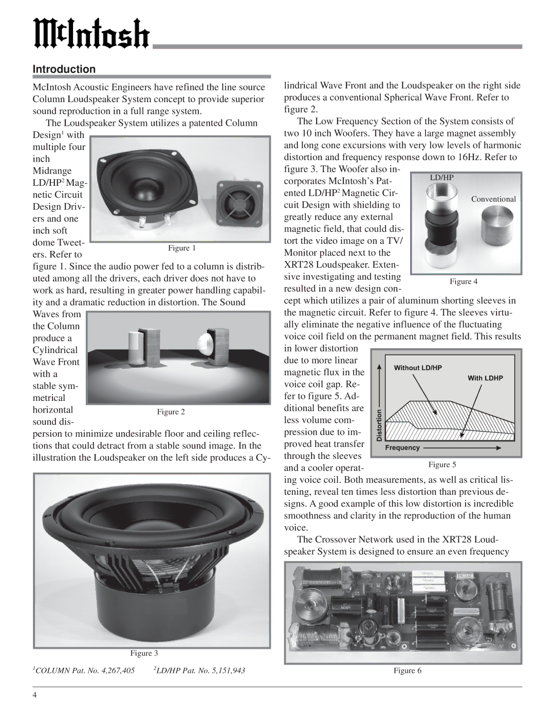
Figure 3
1COLUMN Pat. No. 4,267,405 | 2LD/HP Pat. No. 5,151,943 |
lindrical Wave Front and the Loudspeaker on the right side produces a conventional Spherical Wave Front. Refer to figure 2.
The Low Frequency Section of the System consists of two 10 inch Woofers. They have a large magnet assembly and long cone excursions with very low levels of harmonic distortion and frequency response down to 16Hz. Refer to figure 3. The Woofer also in-
corporates McIntosh’s Pat- | LD/HP | |
ented LD/HP2 Magnetic Cir- | Conventional | |
cuit Design with shielding to | ||
| ||
greatly reduce any external |
| |
magnetic field, that could dis- |
| |
tort the video image on a TV/ |
| |
Monitor placed next to the |
| |
XRT28 Loudspeaker. Exten- |
| |
sive investigating and testing |
| |
Figure 4 | ||
resulted in a new design con- | ||
|
cept which utilizes a pair of aluminum shorting sleeves in the magnetic circuit. Refer to figure 4. The sleeves virtu- ally eliminate the negative influence of the fluctuating voice coil field on the permanent magnet field. This results in lower distortion
due to more linear magnetic flux in the
voice coil gap. Re- fer to figure 5. Ad- ditional benefits are less volume com- pression due to im-
proved heat transfer through the sleeves
and a cooler operat-
ing voice coil. Both measurements, as well as critical lis- tening, reveal ten times less distortion than previous de- signs. A good example of this low distortion is incredible smoothness and clarity in the reproduction of the human voice.
The Crossover Network used in the XRT28 Loud- speaker System is designed to ensure an even frequency
Figure 6
4