IMPORTANT NOTE: The resistors, R1 and R2, are going to dissipate all the power in the divider circuit according to the equation Current = Voltage / Resistance. The higher the value of the resistance (R1 + R2) the less power dissipated by the divider circuit. Here is a simple rule:
For Attenuation of 5:1 or less, no resistor should be less than 10K. For Attenuation of greater than 5:1, no resistor should be less than 1K.
The
6.2 DIFFERENTIAL & SINGLE ENDED INPUTS
Two type of analog inputs are commonly found on A/D boards, they are differential and single ended. Single ended is the less expensive of the two.
COMMON MODE RANGE
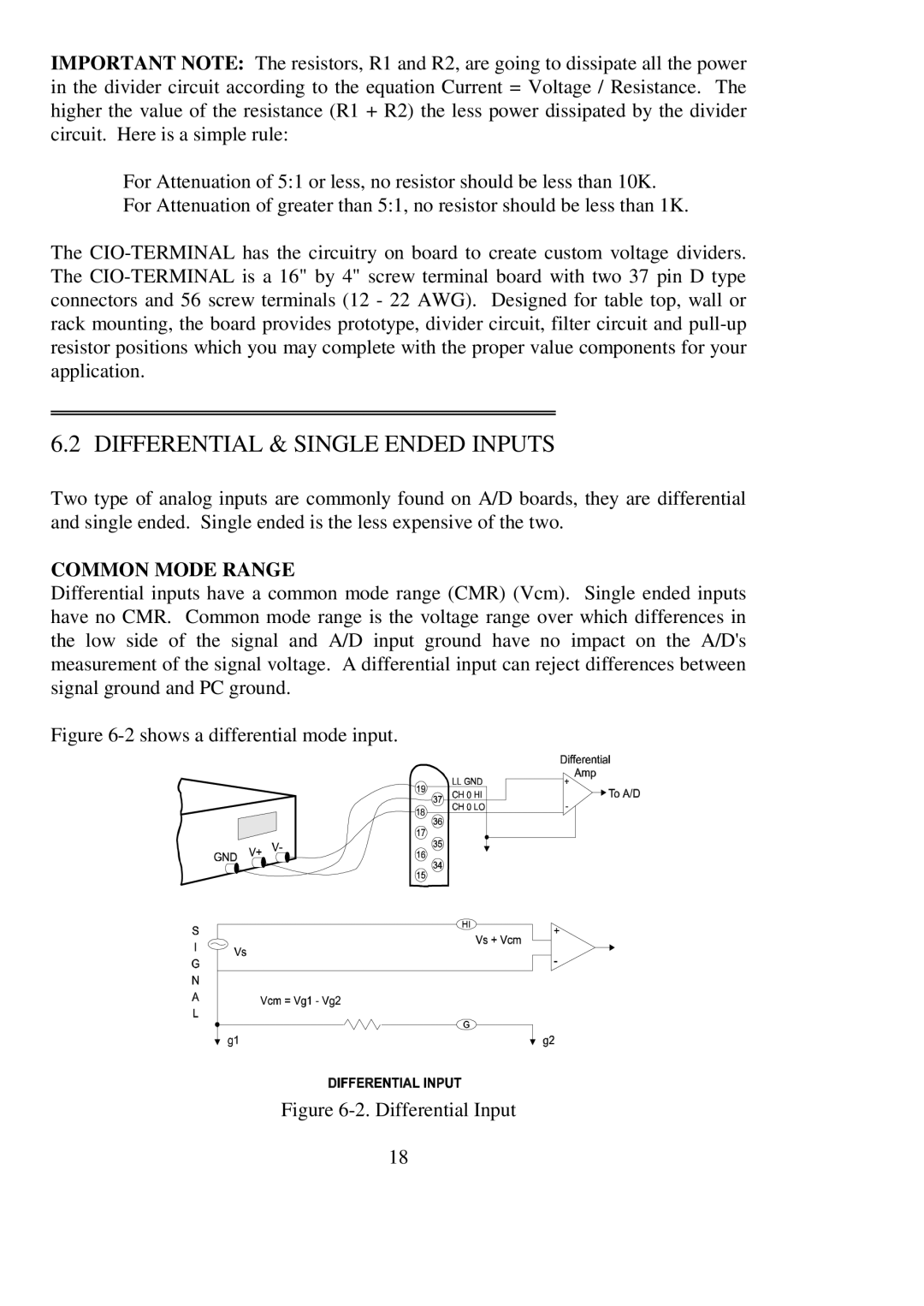
Differential inputs have a common mode range (CMR) (Vcm). Single ended inputs have no CMR. Common mode range is the voltage range over which differences in the low side of the signal and A/D input ground have no impact on the A/D's measurement of the signal voltage. A differential input can reject differences between signal ground and PC ground.
Figure 6-2 shows a differential mode input.
Figure 6-2. Differential Input
18