Manuals
/
Metra Electronics
/
Home Audio
/
Speaker System
Metra Electronics
99-2005 Final Assembly, Final Wiring Connections, Metra / Eia Wiring Code
Models:
99-2005
1
11
12
12
Download
12 pages
38.14 Kb
5
6
7
8
9
10
11
12
Final Wiring Connections
Dash Disassembly
Kit Features
Page 11
Image 11
Page 10
Page 12
Page 11
Image 11
Page 10
Page 12
Contents
99-2005
APPLICATIONS
INSTALLATION INSTRUCTIONS FOR PART
KIT FEATURES
Kit Assembly
99-2005
TABLE OF CONTENTS
Dash Disassembly
Figure A
99-2005 DASH DISASSEMBLY
Continue to kit assembly
CADILLAC ELDORADO CADILLAC SEVILLE
CADILLAC SEVILLE
Figure D
99-2005 DASH DISASSEMBLY
Continue to kit assembly
Continue to kit assembly
CADILLAC DEVILLE
99-2005 DASH DISASSEMBLY
S-Efrom the radio housing. Figure A
99-2005 KIT ASSEMBLY
Continue to kit assembly
the bracket / housing assembly and
Continue to kit assembly
CADILLAC SEVILLE CADILLAC DEVILLE CONCOURS
CONSOLE SHIFT
99-2005 KIT ASSEMBLY
Continue to kit assembly
CADILLAC DEVILLE
99-2005 KIT ASSEMBLY
Continue to kit assembly
DIN HEAD UNIT PROVISION
99-2005 KIT ASSEMBLY
Continue to kit assembly
ISO DIN HEAD UNIT PROVISION
99-2005 KIT ASSEMBLY
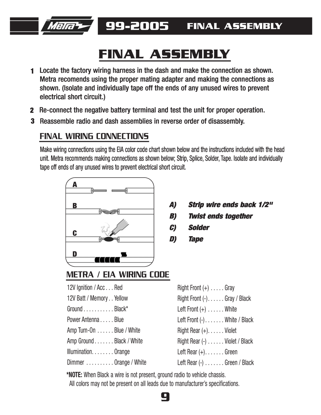
METRA / EIA WIRING CODE
99-2005 FINAL ASSEMBLY
FINAL WIRING CONNECTIONS
FINAL ASSEMBLY
99-2005INSTRUCTIONS
Top
Page
Image
Contents