STACKED ISO DIN HEAD UNIT PROVISION
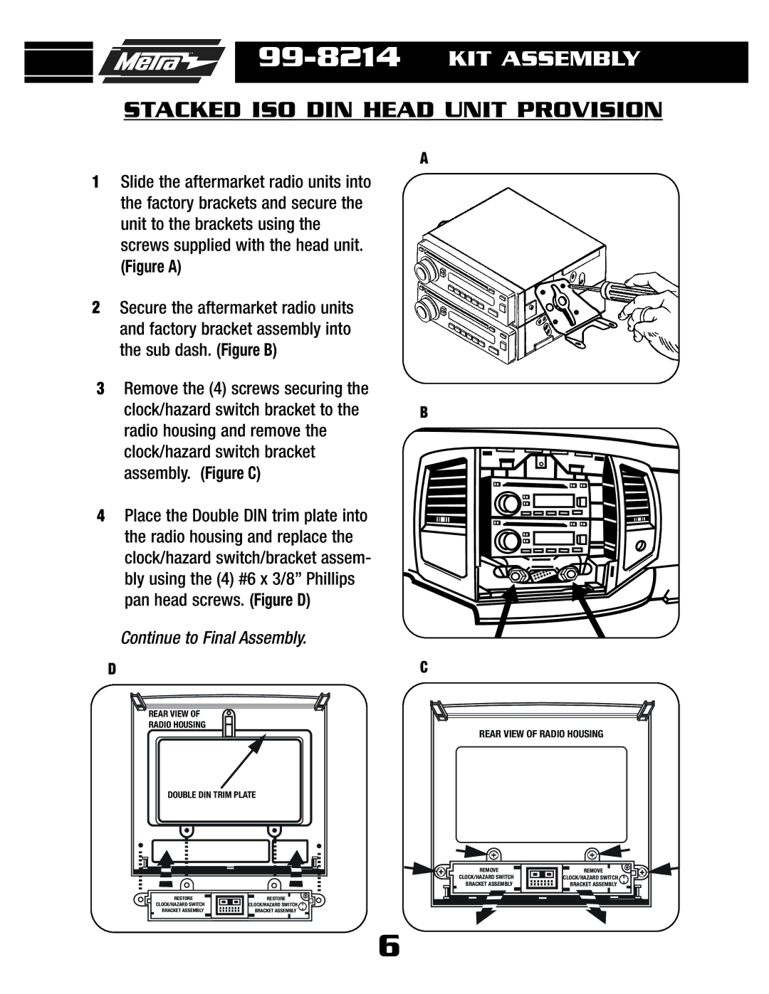
1Slide the aftermarket radio units into the factory brackets and secure the unit to the brackets using the screws supplied with the head unit.
(Figure A)
2Secure the aftermarket radio units and factory bracket assembly into the sub dash. (Figure B)
3Remove the (4) screws securing the clock/hazard switch bracket to the radio housing and remove the clock/hazard switch bracket assembly. (Figure C)
4Place the Double DIN trim plate into the radio housing and replace the clock/hazard switch/bracket assem- bly using the (4) #6 x 3/8” Phillips pan head screws. (Figure D)
Continue to Final Assembly.
D
A
B
C
REAR VIEW OF |
RADIO HOUSING |
DOUBLE DIN TRIM PLATE |
RESTORE | RESTORE |
CLOCK/HAZARD SWITCH | CLOCK/HAZARD SWITCH |
BRACKET ASSEMBLY | BRACKET ASSEMBLY |
REAR VIEW OF RADIO HOUSING | |
REMOVE | REMOVE |
CLOCK/HAZARD SWITCH | CLOCK/HAZARD SWITCH |
BRACKET ASSEMBLY | BRACKET ASSEMBLY |
6