TOOLS REQUIRED FOR INSTALLATION
•Cutting Tool • Small Blade Screwdriver • Tape • Crimping Tool • Connectors (I.E.
APPLICATIONS
MITSUBISHI Eclipse
MITSUBISHI | Endeavor |
*IMPORTANT WARNING
THIS PRODUCT INCLUDES INSTRUCTIONS FOR INSTALLATION WHICH MUST BE CAREFULLY FOLLOWED. THE INSTRUCTIONS ARE WORDED IN SUCH A MANNER TO ASSUME THAT THE INSTALLER IS CAPABLE OF COMPLETING THESE TYPE OF ELECTRONIC INSTALLATIONS. IF YOU ARE UNCLEAR AS TO WHAT YOU ARE INSTRUCTED TO DO OR BELIEVE THAT YOU DO NOT UNDERSTAND THE INSTRUCTIONS SO AS TO PROPERLY AND SAFELY COMPLETE THE INSTALLATION YOU SHOULD CONSULT A TECHNICIAN WHO DOES HAVE THIS KNOWLEDGE AND UNDERSTANDING. FAILURE TO FOLLOW THESE INSTRUCTIONS
CAREFULLY AND TO INSTALL THE INTERFACE AS DESCRIBED COULD CAUSE HARM TO THE VEHICLE OR TO SAFETY SYSTEMS ON THE VEHICLE. INTERFERENCE WITH CERTAIN SAFETY SYSTEMS COULD CAUSE HARM TO PERSONS AS WELL. IF YOU HAVE ANY QUESTIONS IN THIS REGARD PLEASE CALL THE HELP LINE OR THE METRA AT
MITO-01
BEFORE WIRING UP THE MITO-01
*Important: Before beginning any of the following, disconnect the negative battery terminal to prevent an accidental short circuit.
WIRING CONNECTIONS TO BE MADE ON THE VEHICLE SIDE HARNESSES:
1.Connect the Yellow wire to the radio’s 12 volt battery or memory wire.
2.Connect the Red wire to the radios 12 volt ignition or accessory wire.
3.Connect the Black wire with the fork connector to a good ground, like a metal brace in the dash.
4.Connect the Black wire to the radios ground wire.
5.Connect the Orange wire to the radios Illumination wire. If the radio does not have an Illumination wire just tape up the wire.
6.Connect the Blue wire to the radios power antenna turn on wire.
7.Connect the White wire to the radios Left Front (+) speaker wire.
8.Connect the White/Black wire to the radios Left Front
9.Connect the Gray wire to the radios Right Front (+) speaker wire.
10.Connect the Gray/Black wire to the radios Right Front
11.Connect the Green wire to the radios Left Rear (+) speaker wire.
12.Connect the Green/Black wire to the radios Left Rear
13.Connect the Purple wire to the radios Right Rear (+) speaker wire.
14.Connect the Purple/Black wire to the radios Right Rear
If the radio you are installing has navigation built in, the
Follow the steps below to connect these wires to the vehicle:
1.Connect the 2 pin connector with loose leads to the mating connector on the vehicle side harness of the
2.Locate the OBD2 connector which is located beneath the driver’s side dash panel close to the center console and run the Pink and the Blue/Pink wires down to it.
MITSUBISHI Eclipse
OBD2
CONNECTOR ![]()
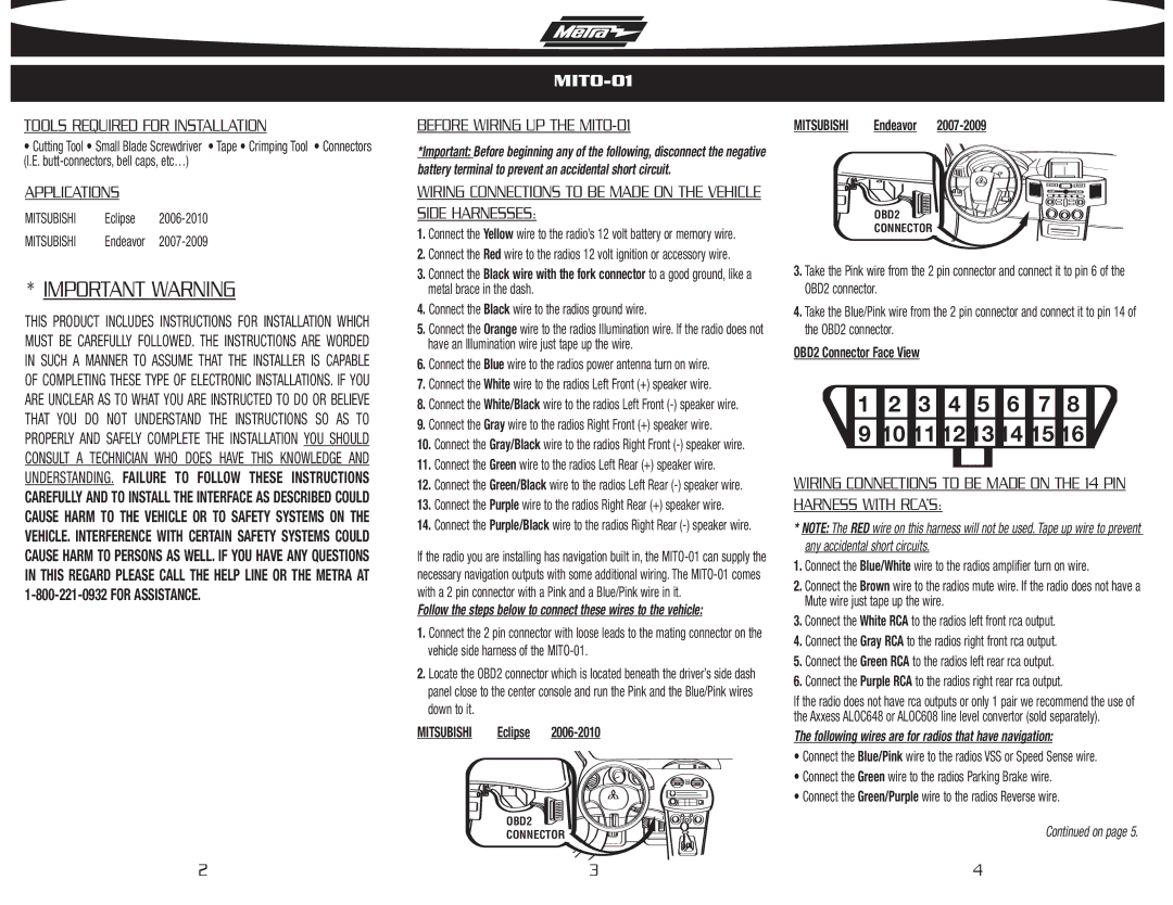
MITSUBISHI Endeavor 2007-2009
OBD2
CONNECTOR ![]()
3.Take the Pink wire from the 2 pin connector and connect it to pin 6 of the OBD2 connector.
4.Take the Blue/Pink wire from the 2 pin connector and connect it to pin 14 of the OBD2 connector.
OBD2 Connector Face View
|
|
|
|
|
|
|
|
1 | 2 | 3 | 4 | 5 | 6 | 7 | 8 |
9 10 11 12 13 14 15 16
WIRING CONNECTIONS TO BE MADE ON THE 14 PIN HARNESS WITH RCA’S:
*NOTE: The RED wire on this harness will not be used. Tape up wire to prevent any accidental short circuits.
1.Connect the Blue/White wire to the radios amplifier turn on wire.
2.Connect the Brown wire to the radios mute wire. If the radio does not have a Mute wire just tape up the wire.
3.Connect the White RCA to the radios left front rca output.
4.Connect the Gray RCA to the radios right front rca output.
5.Connect the Green RCA to the radios left rear rca output.
6.Connect the Purple RCA to the radios right rear rca output.
If the radio does not have rca outputs or only 1 pair we recommend the use of the Axxess ALOC648 or ALOC608 line level convertor (sold separately).
The following wires are for radios that have navigation:
•Connect the Blue/Pink wire to the radios VSS or Speed Sense wire.
•Connect the Green wire to the radios Parking Brake wire.
•Connect the Green/Purple wire to the radios Reverse wire.
Continued on page 5.
2 | 3 | 4 |