MCD-797 specifications
The Metrik Mobile Electronics MCD-797 is an advanced car multimedia system designed to elevate the driving experience through innovative technology and user-friendly features. This head unit blends cutting-edge functionalities with an intuitive interface, making it a top choice for car enthusiasts and casual users alike.One of the standout features of the MCD-797 is its large, responsive touchscreen display. The bright, high-resolution screen is designed for optimal visibility, ensuring that users can easily access information and navigate menus without distraction. The interface is user-friendly, with seamless touch responses and vibrant graphics, making it easy for anyone to operate while on the road.
Another key highlight is the MCD-797's connectivity options. It supports both Apple CarPlay and Android Auto, allowing users to integrate their smartphones with the head unit effortlessly. This enables easy access to navigation apps, music streaming, and hands-free calling. With Bluetooth technology, users can connect their devices wirelessly to listen to their favorite playlists or receive calls without taking their hands off the wheel.
The audio quality of the MCD-797 is considerably impressive. It features a built-in FM/AM radio, as well as a USB port and an auxiliary input for additional audio sources. The advanced equalizer settings allow users to tailor their sound experience according to their preferences, while the powerful built-in amplifier ensures that the sound output is clear and robust, perfect for any genre of music.
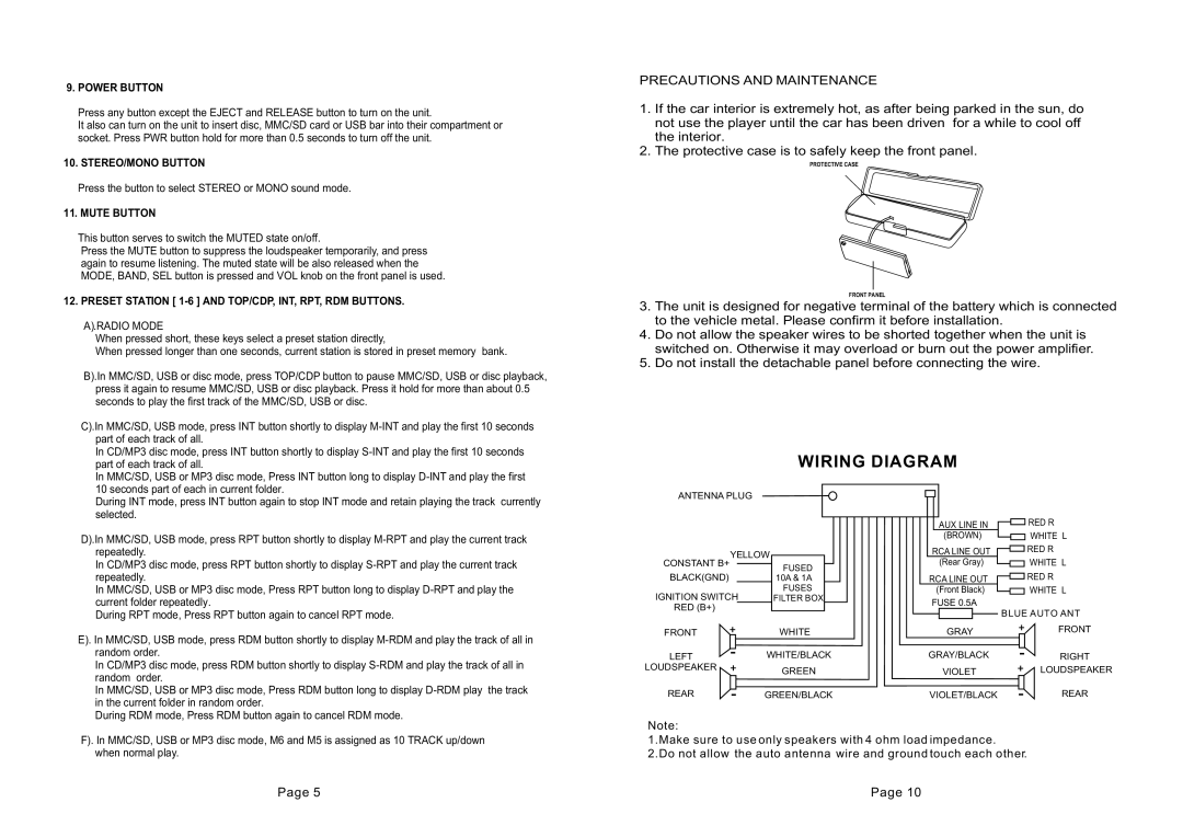
In terms of installation and compatibility, the MCD-797 is designed to fit most standard car stereos, making it a versatile choice for various vehicles. It comes equipped with customizable display settings, allowing users to match the interface with their car’s interior lighting for a cohesive look.
Safety is another focus of the MCD-797, as it includes features such as a rear-view camera input and compatibility with various vehicle sensors, enhancing the driver's awareness and promoting safe driving practices.
Overall, the Metrik Mobile Electronics MCD-797 stands out with its combination of advanced technology, user-centric design, and high-quality audio performance, making it an excellent upgrade for anyone looking to enhance their in-car entertainment experience. Whether you're commuting, road-tripping, or simply running errands, the MCD-797 keeps you connected and entertained on the go.

