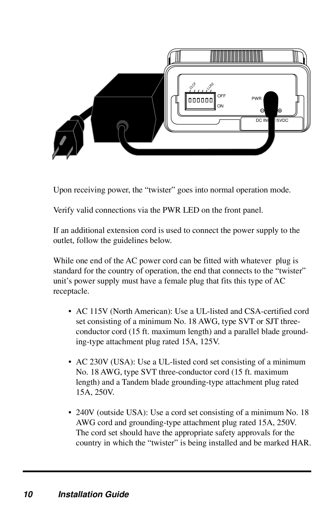
METRObility Optical Systems 2152-DD-01, 2152-AY-01, 2152-77-01, 2152-AF-01 OFF PWR DC INPUT/5VDC

Models: 2152-AA-01 2152-AF-01 2152-JJ-01 2152-AX-01 2152-1J-01 2152-DJ-01 2152-1Y-01 2152-D7-01 2125-34-01 2152-1X-01 2152-AD-01 2152-77-01 2152-1A-01 2152-DD-01 2152-1M-01 2152-1F-01 2152-17-01 2152-A7-01 2135-34-01 2151-AD-01 2125-37-01 2152-DF-01 2152-AY-01 2152-1K-01 2152-AJ-01 2152-1D-01 Gigabit "twister" and SONET "twister

1 20
Download 20 pages 59.88 Kb
Page 10
Image 10

CLCF

LLR2

OFF

ON

PWR

DC INPUT/5VDC

Upon receiving power, the “twister” goes into normal operation mode.

Verify valid connections via the PWR LED on the front panel.

If an additional extension cord is used to connect the power supply to the outlet, follow the guidelines below.

While one end of the AC power cord can be fitted with whatever plug is standard for the country of operation, the end that connects to the “twister” unit’s power supply must have a female plug that fits this type of AC receptacle.

AC 115V (North American): Use a UL-listed and CSA-certified cord set consisting of a minimum No. 18 AWG, type SVT or SJT three- conductor cord (15 ft. maximum length) and a parallel blade ground- ing-type attachment plug rated 15A, 125V.

AC 230V (USA): Use a UL-listed cord set consisting of a minimum No. 18 AWG, type SVT three-conductor cord (15 ft. maximum length) and a Tandem blade grounding-type attachment plug rated 15A, 250V.

240V (outside USA): Use a cord set consisting of a minimum No. 18 AWG cord and grounding-type attachment plug rated 15A, 250V. The cord set should have the appropriate safety approvals for the country in which the “twister” is being installed and be marked HAR.

10 Installation Guide

Page 10
Image 10
METRObility Optical Systems 2152-DD-01, 2152-AY-01, 2152-77-01, 2152-AF-01, 2152-AD-01, 2152-D7-01 manual OFF PWR DC INPUT/5VDC