Installing the Power Supply
Follow the steps outlined below to install the
IMPORTANT
Disconnect all power sources before installing or removing the power supply. A blank panel must remain installed in any empty power supply slot.
Do not apply power to the power supply
while it is out of the platform.
1.Remove the blank panel from the back of the platform.
2.Insert the power supply into the slot. Do not force it into the platform unnecessarily. It should slide in easily and evenly.
3.Push gently until the face panel is flush with the platform.
4.Turn the thumb screws clockwise and tighten to secure the power supply into the platform.
Applying Power
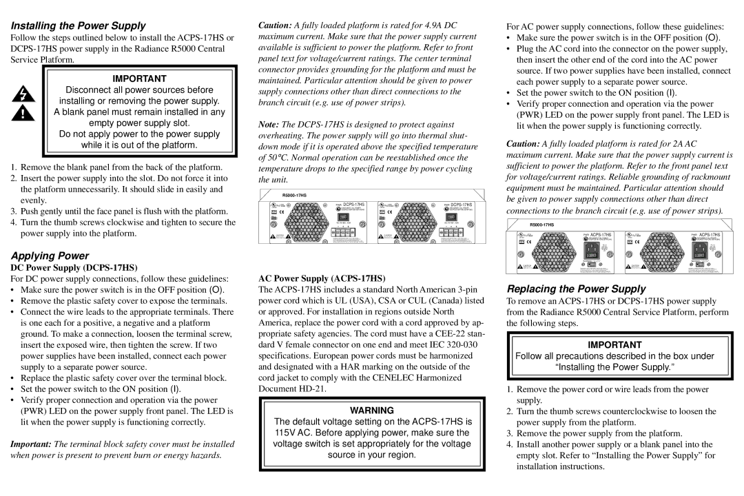
DC Power Supply (DCPS-17HS)
For DC power supply connections, follow these guidelines:
•Make sure the power switch is in the OFF position (O).
•Remove the plastic safety cover to expose the terminals.
•Connect the wire leads to the appropriate terminals. There is one each for a positive, a negative and a platform ground. To make a connection, loosen the terminal screw, insert the exposed wire, then tighten the screw. If two power supplies have been installed, connect each power supply to a separate power source.
•Replace the plastic safety cover over the terminal block.
•Set the power switch to the ON position (I).
•Verify proper connection and operation via the power (PWR) LED on the power supply front panel. The LED is lit when the power supply is functioning correctly.
Important: The terminal block safety cover must be installed when power is present to prevent burn or energy hazards.
Caution: A fully loaded platform is rated for 4.9A DC maximum current. Make sure that the power supply current available is sufficient to power the platform. Refer to front panel text for voltage/current ratings. The center terminal connector provides grounding for the platform and must be maintained. Particular attention should be given to power supply connections other than direct connections to the branch circuit (e.g. use of power strips).
Note: The
|
|
|
|
|
|
C | I.T.E. | PWR | C | I.T.E. | PWR |
US E116552 | US E116552 | ||||
| LISTED | DISCONNECT ALL POWER |
| LISTED | DISCONNECT ALL POWER |
|
| SOURCES BEFORE SERVICING |
|
| SOURCES BEFORE SERVICING |
|
| DC IN 48V, 4.9A |
|
| DC IN 48V, 4.9A |
| CAUTION |
|
| CAUTION |
|
AC Power Supply (ACPS-17HS)
The
WARNING
The default voltage setting on the
For AC power supply connections, follow these guidelines:
•Make sure the power switch is in the OFF position (O).
•Plug the AC cord into the connector on the power supply, then insert the other end of the cord into the AC power source. If two power supplies have been installed, connect each power supply to a separate power source.
•Set the power switch to the ON position (I).
•Verify proper connection and operation via the power (PWR) LED on the power supply front panel. The LED is lit when the power supply is functioning correctly.
Caution: A fully loaded platform is rated for 2A AC maximum current. Make sure that the power supply current is sufficient to power the platform. Refer to the front panel text for voltage/current ratings. Reliable grounding of rackmount equipment must be maintained. Particular attention should be given to power supply connections other than direct connections to the branch circuit (e.g. use of power strips).
C | US E116552 | PWR | C | US E116552 | PWR |
| I.T.E. |
|
| I.T.E. |
|
| LISTED | DISCONNECT ALL POWER |
| LISTED | DISCONNECT ALL POWER |
|
| SOURCES BEFORE SERVICING |
|
| SOURCES BEFORE SERVICING |
AC IN | AC IN |
2A | 2A |
WARNING | WARNING |
CAUTION | CAUTION |
Replacing the Power Supply
To remove an
IMPORTANT
Follow all precautions described in the box under “Installing the Power Supply.”
1.Remove the power cord or wire leads from the power supply.
2.Turn the thumb screws counterclockwise to loosen the power supply from the platform.
3.Remove the power supply from the platform.
4.Install another power supply or a blank panel into the empty slot. Refer to “Installing the Power Supply” for installation instructions.