
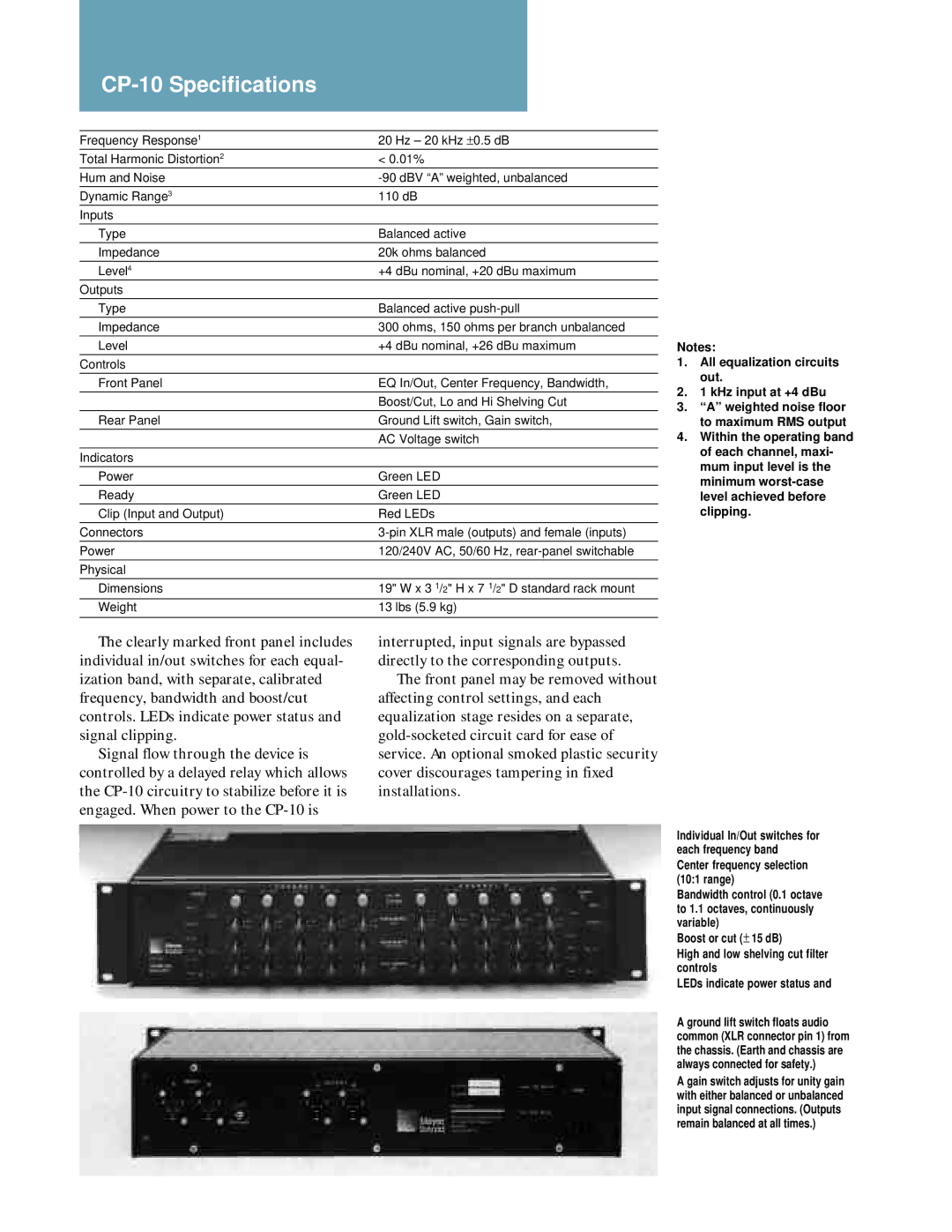
CP-10 specifications
The Meyer Sound CP-10 is a versatile and innovative control processor designed for professional audio applications. Known for its exceptional performance, this product is particularly popular in live sound, installations, and studio environments. The CP-10 combines advanced digital signal processing with a user-friendly interface, making it an essential tool for sound engineers and technicians.One of the main features of the CP-10 is its comprehensive digital signal processing capabilities. It utilizes high-performance algorithms that enable precise equalization, dynamic range control, and delay adjustments. This level of control allows users to tailor the sound to fit a variety of acoustic environments, ensuring optimal audio quality. With up to 30 bands of equalization, the CP-10 can effectively manage feedback and optimize speaker performance across different venues.
The CP-10 incorporates Meyer Sound's renowned intelligent DSP technology, enabling automatic adjustments based on the acoustic properties of the venue. This includes real-time analysis and correction of the audio signal, which enhances clarity and ensures a balanced sound output. This feature is particularly beneficial in complex environments where traditional tuning methods may fall short.
Another key characteristic of the CP-10 is its robust connectivity options. It features multiple input and output channels, allowing seamless integration with a variety of audio sources and systems. Its compact design enables easy installation in rack systems, while its durable construction ensures reliability during demanding live events.
The user interface of the CP-10 is intuitive, featuring a large, high-resolution display that provides real-time feedback on audio settings. This enables sound engineers to make on-the-fly adjustments with ease. Additionally, the CP-10 can be controlled remotely via compatible software, allowing greater flexibility during performances.
Meyer Sound is also known for its commitment to quality, and the CP-10 is no exception. The device is designed to meet the highest standards of audio fidelity, ensuring that every detail of the sound is precisely captured and reproduced. This dedication to excellence has made the CP-10 a preferred choice among sound professionals seeking reliable and high-quality audio solutions in their work.
In summary, the Meyer Sound CP-10 is an exemplary control processor that combines advanced technologies and exceptional features, making it an indispensable asset for any audio professional.