Always “On” UPS Systems Inc.
Connecting the Telephone/Modem/Ethernet Lines
Connect a telephone line, modem line, or 10BaseT line into the telephone/modem/Ethernet surge protection sockets on the back of the UPS. The
Note: This connection is optional. It is not necessary to use this with the UPS.
Caution: The line current limiting feature could be rendered inoperable if improperly installed. Make sure that the line from the wall is plugged into the connector marked “IN”, and the device to be protected (telephone, modem, etc.) is plugged into the connector marked “OUT”.
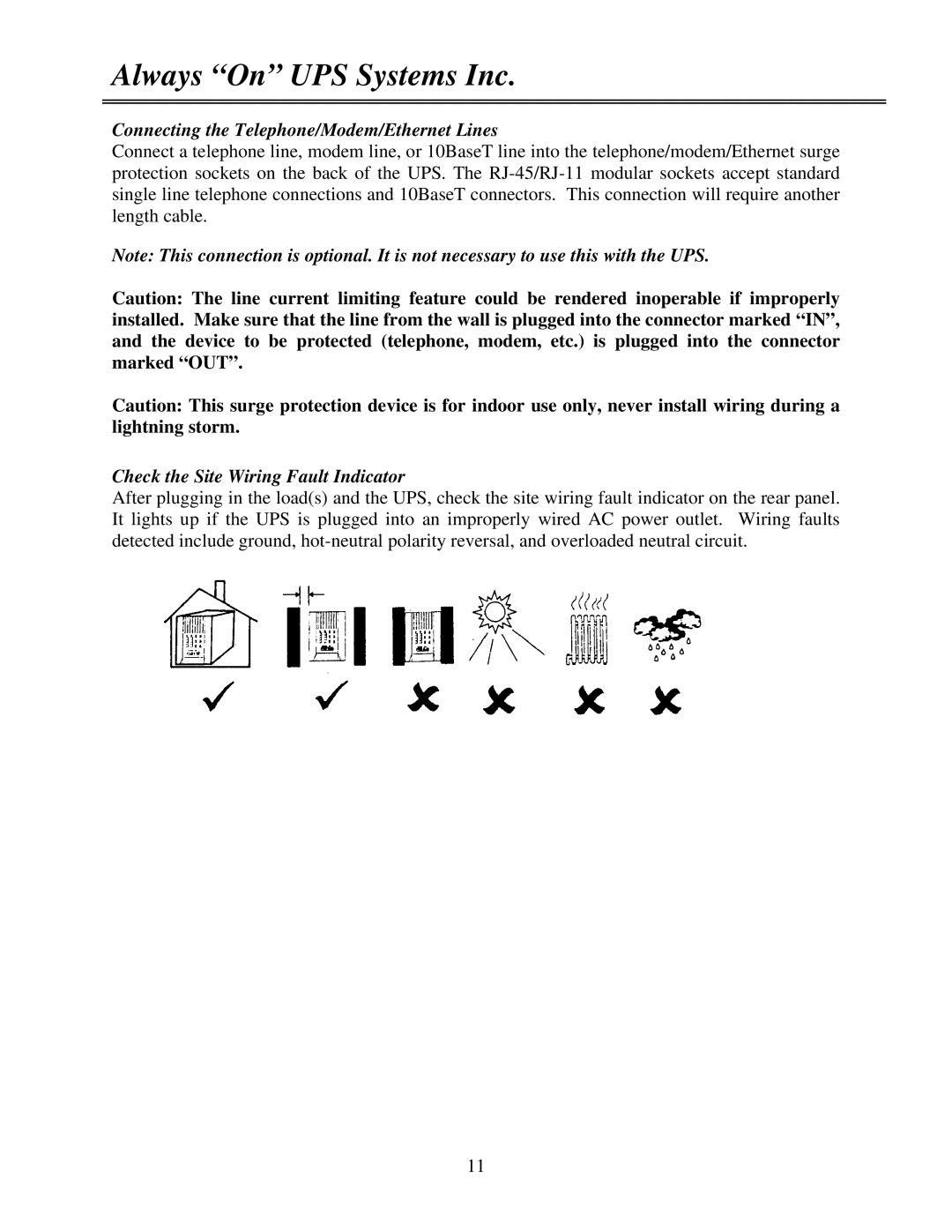
Caution: This surge protection device is for indoor use only, never install wiring during a lightning storm.
Check the Site Wiring Fault Indicator
After plugging in the load(s) and the UPS, check the site wiring fault indicator on the rear panel. It lights up if the UPS is plugged into an improperly wired AC power outlet. Wiring faults detected include ground,
11
