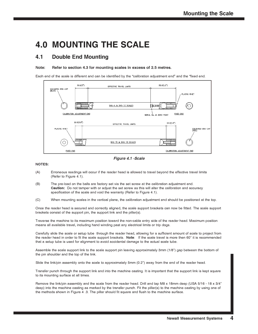
SHG-A* Absolute, SHG-VS, SHG-TS, SHG-TC specifications
Microsoft's SHG product line includes the SHG-TC, SHG-TS, SHG-VS, and SHG-A* Absolute solutions, each designed to cater to varying user needs and preferences within the tech ecosystem. These products demonstrate Microsoft's commitment to innovation, performance, and reliability, making them relevant for consumers from casual users to business professionals.The SHG-TC, or Turbo Charge model, emphasizes efficiency and performance. It boasts an advanced processing unit that optimizes power consumption while delivering maximum output, making it ideal for users who demand high performance without compromising battery life. This model is particularly suited for applications that require significant processing power, such as gaming and graphic design.
The SHG-TS, or Turbo Ultra, builds upon the foundation set by its predecessor with enhanced thermal management techniques. This feature allows users to maintain optimal performance levels even during extended use, minimizing overheating issues. With a focus on multitasking capabilities, the SHG-TS integrates a high-speed SSD and expanded RAM options, providing a swift and responsive experience for users who work with multiple applications simultaneously.
Next in the lineup is the SHG-VS, or Vision Series. This model focuses on visual quality and clarity, making it particularly appealing to designers, photographers, and video editors. Equipped with a high-resolution display and advanced graphics capabilities, the SHG-VS ensures that colors are vibrant and images are sharp. Furthermore, it supports a wide array of creative software, allowing professionals to execute their projects with precision and ease.
Finally, the SHG-A* Absolute serves as Microsoft's premium offering, combining the best features from previous models while incorporating cutting-edge technologies. This model prioritizes user experience with a sleek design, intuitive interface, and seamless integration with other Microsoft services and devices. It includes advanced security features, such as biometric authentication, ensuring that user data remains protected at all times.
In summary, the Microsoft SHG-TC, SHG-TS, SHG-VS, and SHG-A* Absolute represent a diverse range of technological advancements, catering to various user requirements. Each model combines performance, efficiency, and innovative features, positioning Microsoft as a leader in the modern tech landscape. With their commitment to quality and user satisfaction, these products are well-suited for anyone looking to enhance their digital experience.

