Mount the new reflector bracket to the provided holes on the front
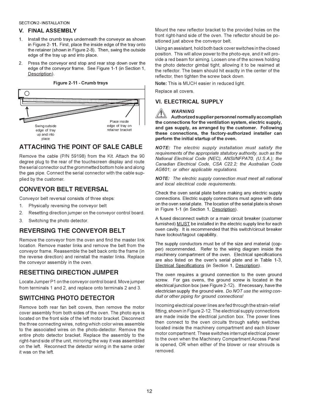
Using an assistant, hold both back cover switches in the closed position. This will allow power to the
Note: This is MUCH easier in reduced light.
Replace all covers.
ATTACHING THE POINT OF SALE CABLE
Remove the cable (P/N 59198) from the Kit. Attach the 90 degree plug to the rear of the touchscreen display and route the serial connector out the grommetted bottom hole and along the gas pipe. Connect the serial connector with the cable sup-
plied by the customer.
CONVEYOR BELT REVERSAL
Conveyor belt reversal consists of three steps:
1.Physically reversing the conveyor belt
2.Resetting direction jumper on the conveyor control board.
3.Switching the photo detector.
REVERSING THE CONVEYOR BELT
Remove the conveyor from the oven and find the master link location. Remove master links and remove the belt from the conveyor frame. Reassemble the belt back onto the frame (in the reverse direction) and reinstall the master links. Replace the conveyor assembly in the oven.
RESETTING DIRECTION JUMPER
Locate Jumper P1 on the conveyor control board. Move jumper from terminals 1 and 2, and replace onto terminals 2 and 3.
SWITCHING PHOTO DETECTOR
Remove both rear fan belt covers, then remove the motor cover assembly from both sides of the oven. The photo eye is located on the front side of the left motor bracket. Disconnect the three connecting wires, noting which color wires assemble to the associated wires on the
Incoming electrical power lines are fed through the
removed.
12