Mount the new reflector bracket to the provided holes on the front
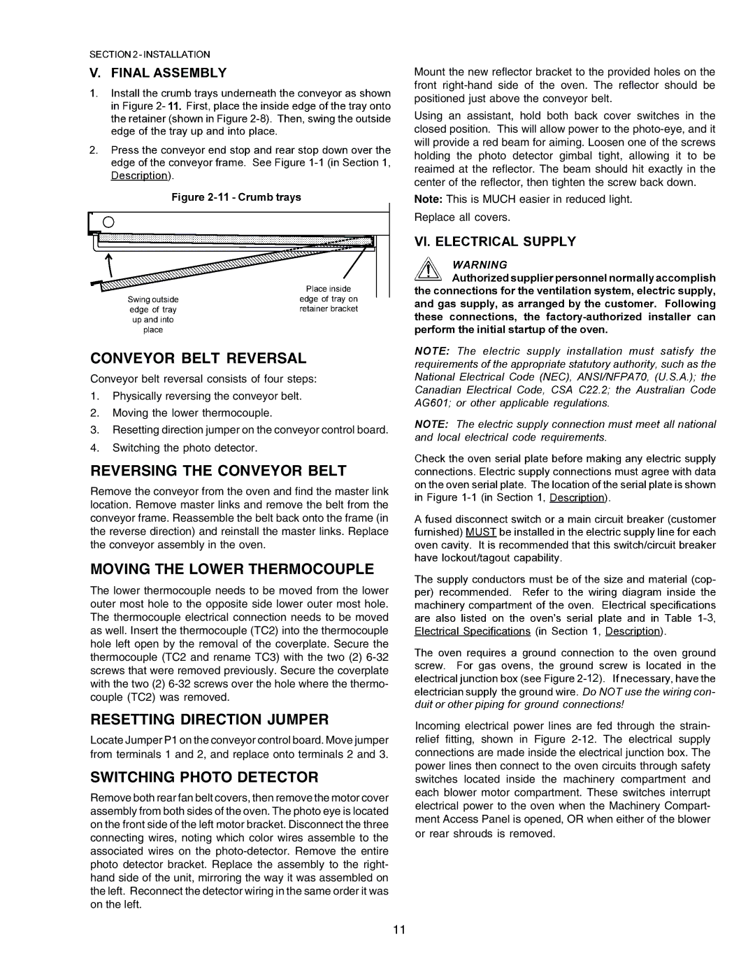
Using an assistant, hold both back cover switches in the closed position. This will allow power to the
Note: This is MUCH easier in reduced light.
Replace all covers.
CONVEYOR BELT REVERSAL
Conveyor belt reversal consists of four steps:
1.Physically reversing the conveyor belt.
2.Moving the lower thermocouple.
3.Resetting direction jumper on the conveyor control board.
4.Switching the photo detector.
REVERSING THE CONVEYOR BELT
Remove the conveyor from the oven and find the master link location. Remove master links and remove the belt from the conveyor frame. Reassemble the belt back onto the frame (in the reverse direction) and reinstall the master links. Replace the conveyor assembly in the oven.
MOVING THE LOWER THERMOCOUPLE
The lower thermocouple needs to be moved from the lower outer most hole to the opposite side lower outer most hole. The thermocouple electrical connection needs to be moved as well. Insert the thermocouple (TC2) into the thermocouple hole left open by the removal of the coverplate. Secure the thermocouple (TC2 and rename TC3) with the two (2)
RESETTING DIRECTION JUMPER
Locate Jumper P1 on the conveyor control board. Move jumper from terminals 1 and 2, and replace onto terminals 2 and 3.
SWITCHING PHOTO DETECTOR
Remove both rear fan belt covers, then remove the motor cover assembly from both sides of the oven. The photo eye is located on the front side of the left motor bracket. Disconnect the three connecting wires, noting which color wires assemble to the associated wires on the
Incoming electrical power lines are fed through the strain- relief fitting, shown in Figure
11