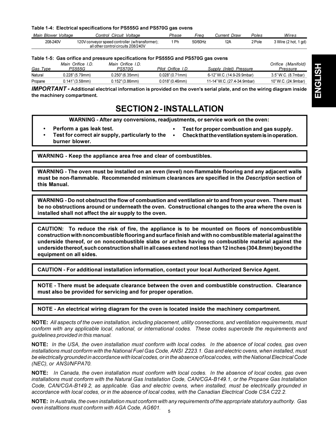
Table 1-4: Electrical specifications for PS555G and PS570G gas ovens
Main Blower Voltage | Control Circuit Voltage | Phase | Freq | Current Draw | Poles | Wires |
120V conveyor speed controller (w/transformer); | 1 Ph | 50/60Hz | 12A | 2 Pole | 3 Wire (2 hot, 1 gd) | |
| all other control circuits 208/240V |
|
|
|
|
|
Table
| Main Orifice I.D. | Main Orifice I.D. |
|
| Orifice (Manifold) |
Gas Type | PS555G | PS570G | Pilot Orifice I.D. | Supply (Inlet) Pressure | Pressure |
Natural | 0.228” (5.79mm) | 0.250" (6.35mm) | 0.028” (0.71mm) | 3.5” W.C. (8.7mbar) | |
Propane | 0.141” (3.58mm) | 0.152" (3.86mm) | 0.018” (0.46mm) | 10” W.C. (24.9mbar) |
IMPORTANT - Additional electrical information is provided on the oven's serial plate, and on the wiring diagram inside the machinery compartment.
SECTION2-INSTALLATION
WARNING - After any conversions, readjustments, or service work on the oven:
• | Perform a gas leak test. | • | Test for proper combustion and gas supply. |
• | Test for correct air supply, particularly to the | • | Checkthattheventilationsystemisinoperation. |
| burner blower. |
|
|
WARNING - Keep the appliance area free and clear of combustibles.
WARNING - The oven must be installed on an even (level)
WARNING - Do not obstruct the flow of combustion and ventilation air to and from your oven. There must be no obstructions around or underneath the oven. Constructional changes to the area where the oven is installed shall not affect the air supply to the oven.
CAUTION: To reduce the risk of fire, the appliance is to be mounted on floors of noncombustible construction with noncombustible flooring and surface finish and with no combustible material against the underside thereof, or on noncombustible slabs or arches having no combustible material against the underside thereof, such construction shall in all cases extend not less than 12 inches (304.8mm) beyond the equipment on all sides.
CAUTION - For additional installation information, contact your local Authorized Service Agent.
NOTE - There must be adequate clearance between the oven and combustible construction. Clearance must also be provided for servicing and for proper operation.
NOTE - An electrical wiring diagram for the oven is located inside the machinery compartment.
NOTE: All aspects of the oven installation, including placement, utility connections, and ventilation requirements, must conform with any applicable local, national, or international codes. These codes supercede the requirements and guidelines provided in this manual.
NOTE: In the USA, the oven installation must conform with local codes. In the absence of local codes, gas oven installations must conform with the National Fuel Gas Code, ANSI Z223.1. Gas and electric ovens, when installed, must be electrically grounded in accordance with local codes, or in the absence of local codes, with the National Electrical Code (NEC), or ANSI/NFPA70.
NOTE: In Canada, the oven installation must conform with local codes. In the absence of local codes, gas oven installations must conform with the Natural Gas Installation Code,
NOTE: In Australia, the oven installation must conform with any requirements of the appropriate statutory authority. Gas
oven installtions must conform with AGA Code, AG601.
5