Hardware Description
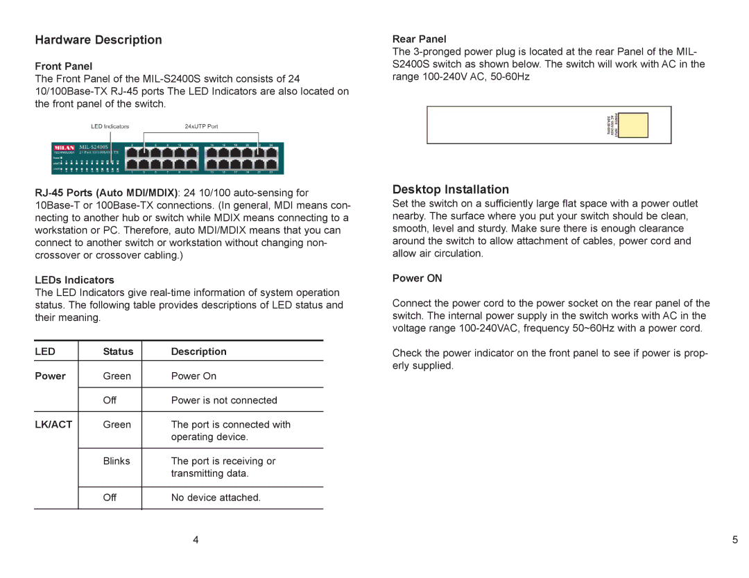
Front Panel
The Front Panel of the
LEDs Indicators
The LED Indicators give
LED | Status | Description |
Power | Green | Power On |
|
|
|
| Off | Power is not connected |
|
|
|
LK/ACT | Green | The port is connected with |
|
| operating device. |
|
|
|
| Blinks | The port is receiving or |
|
| transmitting data. |
|
|
|
| Off | No device attached. |
|
|
|
Rear Panel
The
Desktop Installation
Set the switch on a sufficiently large flat space with a power outlet nearby. The surface where you put your switch should be clean, smooth, level and sturdy. Make sure there is enough clearance around the switch to allow attachment of cables, power cord and allow air circulation.
Power ON
Connect the power cord to the power socket on the rear panel of the switch. The internal power supply in the switch works with AC in the voltage range
Check the power indicator on the front panel to see if power is prop- erly supplied.
4 | 5 |