4-12. Connecting Input Power
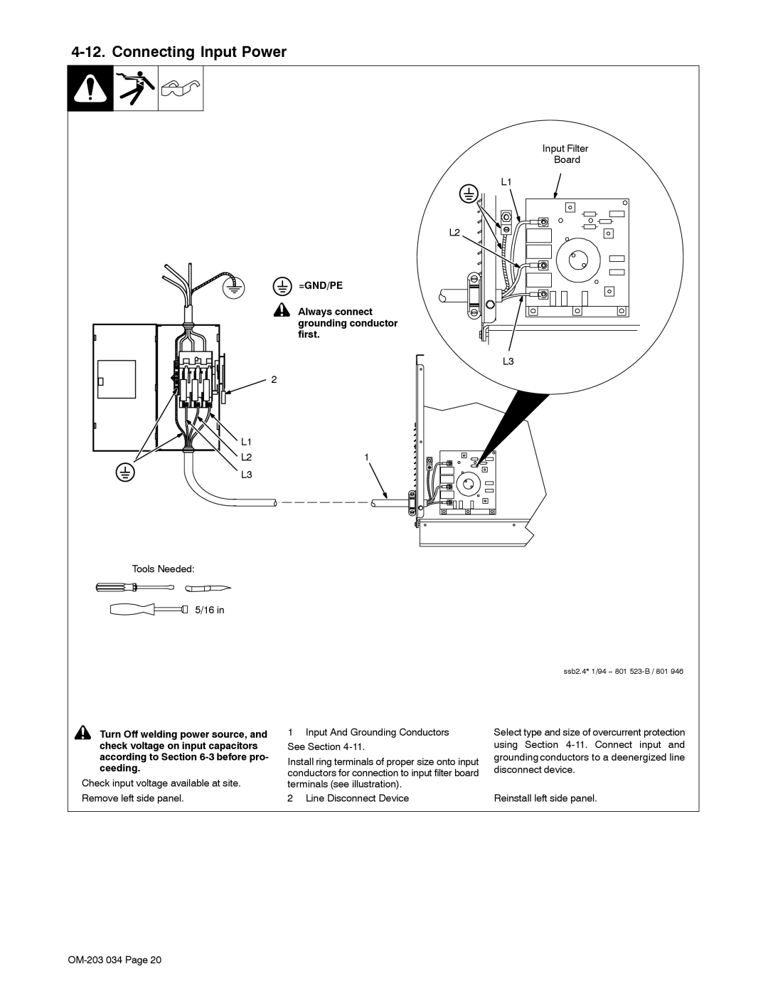
Input Filter
Board
L1
L2
 =GND/PE
! Always connect grounding conductor first.
L3
2
![]() L1
L1
L21
L3
Tools Needed:
5/16 in
ssb2.4* 1/94 − 801
! Turn Off welding power source, and check voltage on input capacitors according to Section
Check input voltage available at site. Remove left side panel.
1Input And Grounding Conductors See Section
Install ring terminals of proper size onto input conductors for connection to input filter board terminals (see illustration).
2 Line Disconnect Device
Select type and size of overcurrent protection using Section
Reinstall left side panel.