SECTION 3 − INSTALLATION
3-1. Gun Recommendation Table
Process | Gun |
|
|
|
|
GMAW − Hard or Corded Wires | M25 Or M40 |
|
|
FCAW − | |
|
|
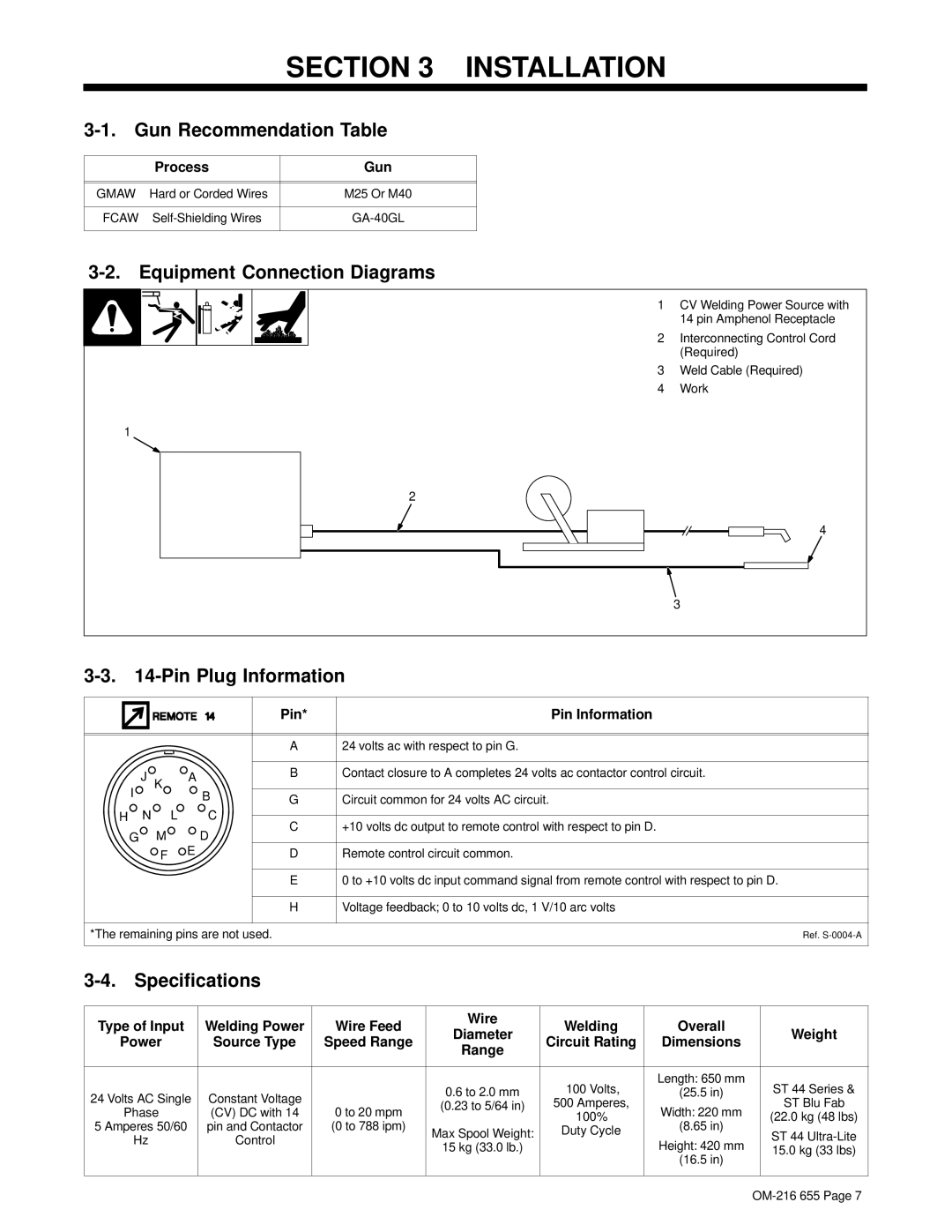
3-2. Equipment Connection Diagrams
|
| 1 | CV Welding Power Source with |
|
|
| 14 pin Amphenol Receptacle |
|
| 2 | Interconnecting Control Cord |
|
|
| (Required) |
|
| 3 | Weld Cable (Required) |
|
| 4 | Work |
| 1 |
|
|
|
| 2 |
|
|
|
| 4 |
|
|
| 3 |
|
|
| |
| Pin* | Pin Information |
|
|
|
| A | 24 volts ac with respect to pin G. | |
J | K | A | B | Contact closure to A completes 24 volts ac contactor control circuit. | |
|
| ||||
I |
| B | G | Circuit common for 24 volts AC circuit. | |
H N | L | C | C | +10 volts dc output to remote control with respect to pin D. | |
G | M | D | |||
|
| ||||
| F | E | D | Remote control circuit common. | |
|
|
| E | 0 to +10 volts dc input command signal from remote control with respect to pin D. | |
|
|
| H | Voltage feedback; 0 to 10 volts dc, 1 V/10 arc volts | |
*The remaining pins are not used. |
| Ref. | |||
3-4. Specifications
Type of Input | Welding Power | Wire Feed | Wire | Welding | Overall |
| |
Diameter | Weight | ||||||
Power | Source Type | Speed Range | Circuit Rating | Dimensions | |||
Range |
| ||||||
|
|
|
|
|
| ||
|
|
|
|
|
|
| |
|
|
| 0.6 to 2.0 mm | 100 Volts, | Length: 650 mm | ST 44 Series & | |
24 Volts AC Single | Constant Voltage |
| (25.5 in) | ||||
0 to 20 mpm | (0.23 to 5/64 in) | 500 Amperes, | Width: 220 mm | ST Blu Fab | |||
Phase | (CV) DC with 14 | ||||||
| 100% | (22.0 kg (48 lbs) | |||||
5 Amperes 50/60 | pin and Contactor | (0 to 788 ipm) |
| (8.65 in) | |||
Max Spool Weight: | Duty Cycle | ST 44 | |||||
Hz | Control |
| Height: 420 mm | ||||
| 15 kg (33.0 lb.) |
| 15.0 kg (33 lbs) | ||||
|
|
|
| ||||
|
|
|
|
| (16.5 in) |
| |
|
|
|
|
|
|
|