Manuals
/
Miller Electric
/
Power Tools
/
Welder
Miller Electric
ST 44 Series
owner manual
Electrical Diagram
Models:
ST 44 Series
1
17
28
28
Download
28 pages
37.72 Kb
14
15
16
17
18
19
20
21
Troubleshooting
Specifications
Parts list
Electrical Diagram
Symbol Usage
ST Blu Fab Wire Feed Assembly
Maintenance
1. ST 44 Complete Assembly
Safety
Page 17
Image 17
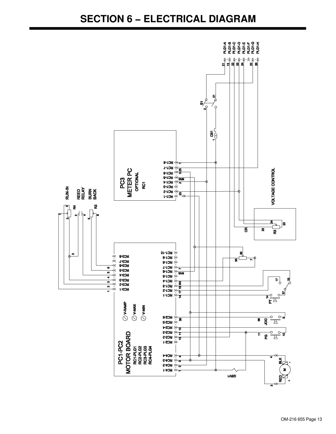
SECTION 6 − ELECTRICAL DIAGRAM
OM-216
655 Page 13
Page 16
Page 18
Page 17
Image 17
Page 16
Page 18
Contents
Description
OM-216 655E 2007−03
Processes
From Miller to You
Table of Contents
DecstatMilan6/05
Directives
Standards
Marks a special safety message
Symbol Usage
Arc Welding Hazards
Electric Shock can kill
Welding can cause fire or explosion
ARC Rays can burn eyes and skin
Flying Metal can injure eyes
Buildup of GAS can injure or kill
California Proposition 65 Warnings
About Pacemakers
Principal Safety Standards
EMF Information
− Definitions
+ +
Made In the EEC2003
Symbols and Definitions
Rating Label
Equipment Connection Diagrams
− Installation
Specifications
Gun Recommendation Table
Aligning Wire Guide And Drive Rolls
Connecting Welding Gun And Weld Cable
Installing Wire Guide And Drive Roll
ST Blu Fab Panel Controls
− Operation
ST 44 Series Panel Controls
Run-In Control and Burnback Control
Use control to set wire feed speed before arc initiation
Run-In Control
Burnback Control
Months
− Maintenance & Troubleshooting
Routine Maintenance
Troubleshooting
− Electrical Diagram
ST 44 Complete Assembly Optional Equipment Shown
− Parts List
−1. ST 44 Complete Assembly
Roll Wire Drive Assembly All Models
ST Blu Fab Wire Feed Assembly
000083432
656005029 Insulator, drive assembly 206219
Cogged
Drive Roll And Wire Guide Kits 4 Drive Roll
1.2 mm
Page
Page
Effective January 1
Your distributor and/or equipment manufacturer’s
For assistance in filing or settling claims, contact
Transportation Department
ITW Welding Products Italy S.r.l. Via Privata Iseo, 6/E
Top
Page
Image
Contents