Manuals
/
Miller Electric
/
Power Tools
/
Welder
Miller Electric
XLT 135, XLT 165
warranty
Electrical Diagram, Circuit Diagram For 115 VAC Model
Models:
XLT 135, XLT 165
XLT 165, XLT 135
1
31
48
48
Download
48 pages
13.4 Kb
28
29
30
31
32
33
34
35
Troubleshooting
Specs
Poor Weld Bead Characteristics
Install
Parts list
Electrical Diagram
Symbol Usage
Threading Welding Wire
Warranty
Flow Adjust
Page 31
Image 31
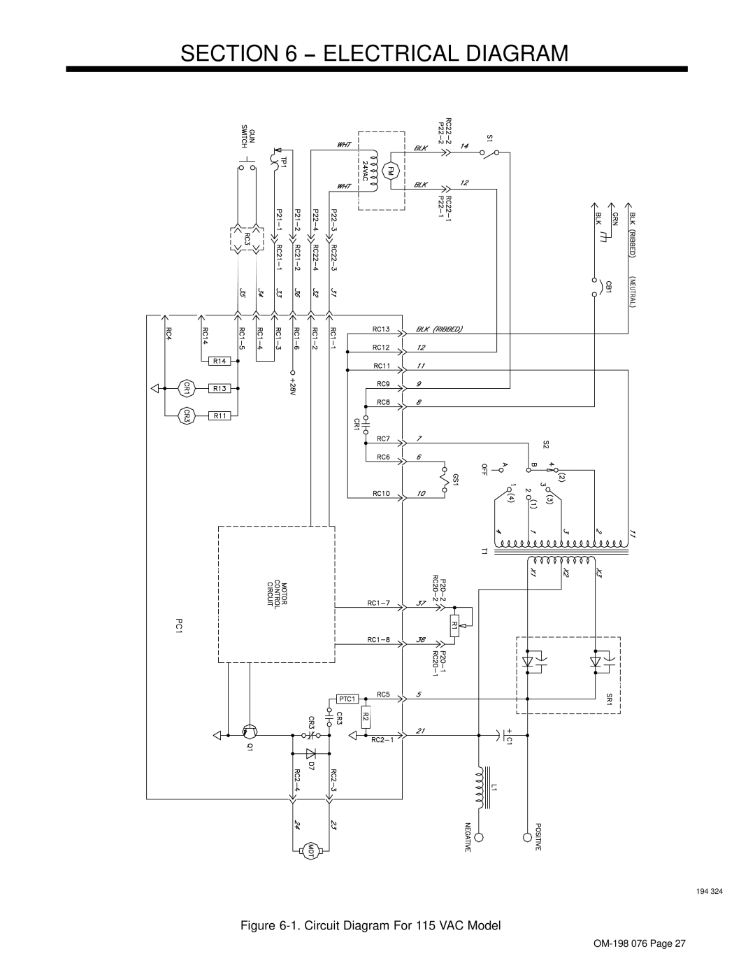
SECTION 6 − ELECTRICAL DIAGRAM
(NEUTRAL)
194 324
Figure
6-1.
Circuit Diagram For 115 VAC Model
OM-198
076 Page 27
Page 30
Page 32
Page 31
Image 31
Page 30
Page 32
Contents
April
OM-198 076A
Processes
Description
Page
Table of Contents
Page
Electric Shock can kill
Symbol Usage
Marks a special safety message
Arc Welding Hazards
Buildup of GAS can injure or kill
ARC Rays can burn eyes and skin
Welding can cause fire or explosion
Flying Metal can injure eyes
Principal Safety Standards
About Pacemakers
EMF Information
LES Fumées ET LES GAZ peuvent être dangereux
Signification des symboles
− Consignes DE Securite − Lire Avant Utilisation
UN Choc Électrique peut tuer
LE Bruit peut affecter l’ouïe
LE Soudage peut provoquer un incendie ou une explosion
DES Particules Volantes peuvent blesser les yeux
DES Pièces Chaudes peuvent pro- voquer des brûlures graves
DES Organes Mobiles peuvent provoquer des blessures
Risque D’INCENDIE OU
LA Chute DE L’APPAREIL peut blesser
’EMPLOI Excessif peut
Information sur les champs électromagnétiques
Principales normes de sécurité
Consignes relatives aux stimulateurs cardiaques
Specifications
− Specifications
VAC Model
Overheating
Duty Cycle And Overheating
Output Duty Cycle %
Output Amperes
Volt-Ampere Curves
Installing Welding Gun Installing Work Clamp
− Installation
Changing Polarity
Process/Polarity Table
Regulator/flowmeter and CO2 cylinder CO2 Gas
Installing Gas Supply
Flow Adjust
CO2 Adapter Customer Sup- plied
Up to 200 ft 61 m
Rating Label
Grounded Receptacle
Volt, 20 ampere individual
See Section
Do not move or operate unit where it could tip
Plug
Receptacle
Adjusting Hub Tension
Electrical Service Guide For 230 VAC Model
Installing Wire Spool And Adjusting Hub Tension
Standard Wire Spool 8 Lb Wire Spool 4
Threading Welding Wire
Controls
Voltage Switch
Power Switch OM-198 076
− Operation
Weld Parameters For 115 VAC Model
Weld Parameters For 230 VAC Model
Drive Motor Protection
− Maintenance &TROUBLESHOOTING
Routine Maintenance
Overload Protection
Turn Off power before replacing contact tip
Changing Drive Roll Or Wire Inlet Guide
Replacing Gun Contact Tip
Disconnect gun from unit
Cleaning Or Replacing Gun Liner
To Reassemble Gun
Replacing Switch And/Or Head Tube
Trouble Remedy
Troubleshooting Table
Does not run
Circuit Diagram For 115 VAC Model
− Electrical Diagram
Circuit Diagram For 230 VAC Model
Typical MIG Process Connections
− MIG Welding Gmaw Guidelines
Select Voltage
Typical MIG Process Control Settings
Wire Size Amperage Range
Select Wire Size Recommendation Wire Speed
Holding And Positioning Welding Gun
ShortNormalLong
Conditions That Affect Weld Bead Shape
Push Perpendicular Drag
Short Normal Long
Good Weld Bead Characteristics
Poor Weld Bead Characteristics
Gun Movement During Welding
Possible Causes Corrective Actions
Troubleshooting − Excessive Spatter
Troubleshooting − Porosity
Troubleshooting − Excessive Penetration
Troubleshooting − Incomplete Fusion
Troubleshooting − Lack Of Penetration
Troubleshooting − Burn-Through
Direction
Troubleshooting − Waviness Of Bead
Troubleshooting − Distortion
Base metal to move
Application
Common MIG Shielding Gases
Flat & Horizontal1 Fillet
Main Assembly
− Parts List
Dia Part Description Quantity Mkgs
Gun
024 .6 and .030/.035 .8
042
024 .6 and .045
Page
Warranty
Owner’s Record
Top
Page
Image
Contents