•Use vacuum only with specifically designated battery packs. Use of any other battery packs may create a risk of injury and fire.
•When battery pack is not in use, keep it away from other metal objects like paper clips, coins, keys, nails, screws, or other small metal objects that can make a connection from one terminal to another. Shorting the battery terminals together may cause burns or a fire.
•Do not use damaged battery pack or vacuum. If battery pack or appliance are not working as they should, have been dropped, damaged, left outdoors, or dropped into water, return them to a service center.
SERVICE
•Have your power tool serviced by a qualified repair person using only identical replacement parts. This will ensure that the safety of the power tool is maintained.
READ AND SAVE
ALL INSTRUCTIONS FOR FUTURE USE
SPECIFICATIONS
Cat. No. | Volts | Capacity | For use with | Battery packs for use |
Battery Packs: | with chargers: | |||
28 DC | 2 Gal. | |||
|
| (7.5 L) |
|
|
| 18 DC | 2 Gal. | ||
|
| |||
|
|
| ||
|
| (7.5 L) | ||
|
|
| ||
|
|
| ||
|
|
| ||
|
|
|
| |
|
|
| 18 V |
|
ASSEMBLY
SYMBOLOGY
| Underwriters Laboratories, Inc., |
| Direct Current |
| United States and Canada |
| |
|
|
| |
|
|
|
|
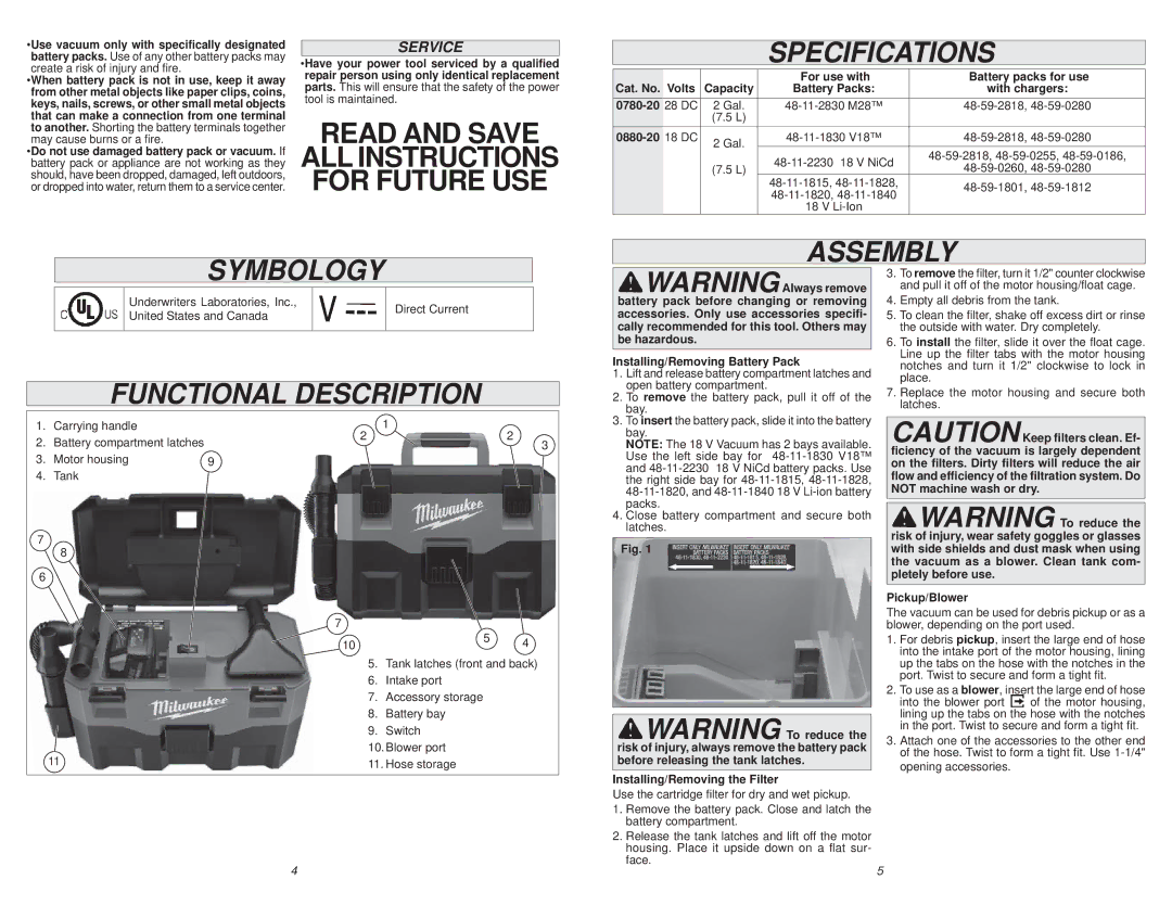
FUNCTIONAL DESCRIPTION
![]()
![]() WARNINGAlways remove battery pack before changing or removing accessories. Only use accessories specifi- cally recommended for this tool. Others may be hazardous.
WARNINGAlways remove battery pack before changing or removing accessories. Only use accessories specifi- cally recommended for this tool. Others may be hazardous.
Installing/Removing Battery Pack
1. | Lift and release battery compartment latches and |
2. | open battery compartment. |
To remove the battery pack, pull it off of the | |
| bay. |
3.To remove the filter, turn it 1/2" counter clockwise and pull it off of the motor housing/float cage.
4.Empty all debris from the tank.
5.To clean the filter, shake off excess dirt or rinse the outside with water. Dry completely.
6.To install the filter, slide it over the float cage. Line up the filter tabs with the motor housing notches and turn it 1/2" clockwise to lock in place.
7.Replace the motor housing and secure both latches.
1.Carrying handle
2.Battery compartment latches
3. | Motor housing | 9 |
4. | Tank |
|
7
8
6
11
7
10
1
22
3
5 4
5.Tank latches (front and back)
6.Intake port
7.Accessory storage
8.Battery bay
9.Switch
10.Blower port
11.Hose storage
3. To insert the battery pack, slide it into the battery |
bay. |
NOTE: The 18 V Vacuum has 2 bays available. |
Use the left side bay for |
and |
the right side bay for |
packs. |
4. Close battery compartment and secure both |
latches. |
Fig. 1
![]()
![]() WARNING To reduce the risk of injury, always remove the battery pack before releasing the tank latches.
WARNING To reduce the risk of injury, always remove the battery pack before releasing the tank latches.
Installing/Removing the Filter
Use the cartridge filter for dry and wet pickup.
1.Remove the battery pack. Close and latch the battery compartment.
2.Release the tank latches and lift off the motor housing. Place it upside down on a flat sur- face.
CAUTIONKeep filters clean. Ef- ficiency of the vacuum is largely dependent on the filters. Dirty filters will reduce the air flow and efficiency of the filtration system. Do NOT machine wash or dry.
![]()
![]() WARNING To reduce the risk of injury, wear safety goggles or glasses with side shields and dust mask when using the vacuum as a blower. Clean tank com- pletely before use.
WARNING To reduce the risk of injury, wear safety goggles or glasses with side shields and dust mask when using the vacuum as a blower. Clean tank com- pletely before use.
Pickup/Blower
The vacuum can be used for debris pickup or as a blower, depending on the port used.
1.For debris pickup, insert the large end of hose into the intake port of the motor housing, lining up the tabs on the hose with the notches in the port. Twist to secure and form a tight fit.
2.To use as a blower, insert the large end of hose
into the blower port of the motor housing,
lining up the tabs on the hose with the notches in the port. Twist to secure and form a tight fit.
3.Attach one of the accessories to the other end of the hose. Twist to form a tight fit. Use
4 | 5 |