ASSEMBLY
OPERATION
![]() WARNING Recharge only with the charger specified for the battery. For specific charging instructions, read the operator’s manual supplied with your charger and bat- tery.
WARNING Recharge only with the charger specified for the battery. For specific charging instructions, read the operator’s manual supplied with your charger and bat- tery.
Inserting/Removing the Battery
To remove the battery, push in the release buttons and pull the battery pack away from the tool.
To insert the battery, slide the pack into the body of the tool. Make sure it latches securely into place.
![]() WARNING Always remove battery pack before changing or removing acces- sories. Only use accessories specifically recommended for this tool. Others may be hazardous.
WARNING Always remove battery pack before changing or removing acces- sories. Only use accessories specifically recommended for this tool. Others may be hazardous.
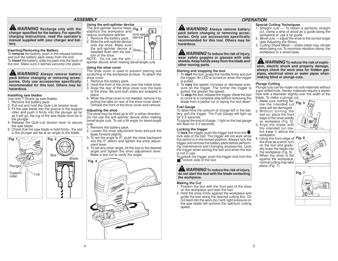
Installing saw blades
Use only
1.Remove the battery pack.
2.Pull out and hold the
3.Fit the saw blade into the groove in the support roller and push it firmly into the plunger as far as it will go; the lug of the saw blade must be in the plunger.
4.Release the
5.Check that the saw blade is held firmly; the slot in the plunger will be at an angle to the blade.
Using the anti-splinter device
The | Fig. 3 |
stabilize the workpiece and | |
reduce workpiece splinter. | |
1. Remove the battery pack. | device |
2. Slide the |
|
onto the shoe. Make sure |
|
the | Shoe |
installed flush with the bot- |
|
tom of the shoe. |
|
NOTE: Do not use the anti- |
|
splinter device when making bevel/angle cuts. | |
Using the shoe cover
The shoe cover is used to prevent marring and scratching of the workpiece surface. To attach the shoe cover:
1.Remove the battery pack.
2.Hook the front of the cover over the metal shoe.
3.Snap the rear of the shoe cover over the back of the shoe. Be sure both sides are snapped in place.
4.When the shoe cover is not needed, remove it by pulling the tabs on rear of the shoe cover down. Unhook the front of the shoe cover and remove.
Adjusting the shoe
The shoe may be tilted up to 45° in either direction. Do not use the
1. | Remove the battery pack. |
2. | Loosen the shoe adjustment lever and pull the |
| base forward slightly. |
![]() WARNING Always remove battery pack before changing or removing acces- sories. Only use accessories specifically recommended for this tool. Others may be hazardous.
WARNING Always remove battery pack before changing or removing acces- sories. Only use accessories specifically recommended for this tool. Others may be hazardous.
![]() WARNING To reduce the risk of injury, wear safety goggles or glasses with side shields. Keep hands away from the blade and other moving parts.
WARNING To reduce the risk of injury, wear safety goggles or glasses with side shields. Keep hands away from the blade and other moving parts.
Starting and stopping the tool
1.To start the tool, grasp the handle firmly and pull the trigger. An LED is turned on when the trigger is pulled.
2.To vary the speed, increase or decrease pres- sure on the trigger. The further the trigger is pulled, the greater the speed.
3.To stop the tool, release the trigger. Allow the tool to come to a complete stop before removing the blade from a partial cut or laying the tool down.
Fuel Gauge
To determine the amount of charge left in the bat- tery, pull the trigger. The Fuel Gauge will light up for
To signal the end of charge, 1 light on the fuel gauge will flash for
Locking the trigger
To lock the trigger, push the trigger lock from the
Fig. 1 |
|
Plunger |
|
Support | Lug |
roller |
|
Fig. 2
Slot ![]()
Blade
3. | To set the angle to 0°, push the shoe backward |
| into the 0° detent and tighten the shoe adjust- |
4. | ment lever. |
To set any other angle, tilt the tool to the desired | |
| angle and tighten the shoe adjustment lever. |
| Make a test cut to verify the angle. |
Fig. 4 |
lock side of the tool. The trigger will not work while the switch is in the locked position. Always lock the trigger and remove the battery pack before perform- ing maintenance and changing accessories. Lock the trigger when storing the tool and when the tool is not in use.
To unlock the trigger, push the trigger lock from the unlock side of the tool.
![]() WARNING To reduce the risk of injury, do not start the tool with the blade contacting the workpiece.
WARNING To reduce the risk of injury, do not start the tool with the blade contacting the workpiece.
Making the Cut
1.Position the tool with the front part of the shoe on the workpiece and start the tool.
2.Hold the shoe firmly against the workpiece and guide the tool along the desired cutting line. Do not feed into the work too hard, light pressure on the saw blade will achieve the optimum cutting speed.
4 | 5 |