ASSEMBLY | OPERATION |
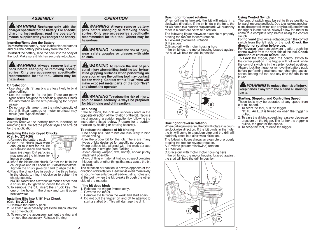
Bracing for forward rotation
When drilling in forward, the bit will rotate in a
Using Control Switch
The control switch may be set to three positions:
![]() WARNING Recharge only with the charger specified for the battery. For specific charging instructions, read the operator’s manual supplied with your charger and battery.
WARNING Recharge only with the charger specified for the battery. For specific charging instructions, read the operator’s manual supplied with your charger and battery.
Inserting/Removing the Battery
To remove the battery, push in the release buttons and pull the battery pack away from the tool.
To insert the battery, slide the pack into the body of the tool. Make sure it latches securely into place.
![]() WARNING Always remove battery pack before changing or removing acces- sories. Only use accessories specifically recommended for this tool. Others may be hazardous.
WARNING Always remove battery pack before changing or removing acces- sories. Only use accessories specifically recommended for this tool. Others may be hazardous.
Bit Selection
•Use sharp bits. Sharp bits are less likely to bind when drilling.
•Use the proper bit for the job. There are many types of bits designed for specific purposes. Check the information on the bit's packaging for proper usage.
•Do not use bits larger than the rated capacity of the drill. Gear damage or motor overload may result (see "Specifications").
Installing Bits
Always remove the battery before inserting or removing bits. Select the proper style and size bit for the application.
Installing Bits into Keyed Chucks
(Cat. No ![]() 1. Remove the battery pack.
1. Remove the battery pack. ![]()
![]()
![]()
![]()
![]()
![]()
![]()
![]()
![]()
![]()
![]()
![]()
![]()
![]() 2. Open the chuck jaws wide
2. Open the chuck jaws wide ![]()
![]()
![]()
![]()
![]()
![]()
![]()
![]()
![]()
![]()
![]()
![]()
![]()
![]() enough to insert the bit. Be
enough to insert the bit. Be ![]()
![]()
![]()
![]()
![]()
![]()
![]()
![]()
![]()
![]()
![]()
![]()
![]()
![]()
![]()
![]()
![]()
![]()
![]()
![]()
![]()
sure the bit shank and chuck jaws are clean. Dirt particles may prevent the bit from lin-
ing up properly.
3.Insert the bit into the chuck. Center the bit in the chuck jaws and lift it about 1/16" off of the bottom. Tighten the chuck jaws by hand to align the bit.
4.Place the chuck key in each of the three holes in the chuck, turning it clockwise to tighten the chuck securely.
NOTE: Never use a wrench or means other than a chuck key to tighten or loosen the chuck.
5.To remove the bit, insert the chuck key into one of the holes in the chuck and turn it coun- terclockwise.
Installing Bits into 7/16" Hex Chuck (Cat. No 2708-20)
1.Remove the battery pack.
2.To attach an accessory, press the shank into the hex drive chuck.
3.To remove the accessory, pull out the ring and remove the accessory. Release the ring.
![]() WARNING Always remove battery pack before changing or removing acces- sories. Only use accessories specifically recommended for this tool. Others may be hazardous.
WARNING Always remove battery pack before changing or removing acces- sories. Only use accessories specifically recommended for this tool. Others may be hazardous.
![]() WARNING To reduce the risk of injury, wear safety goggles or glasses with side shields.
WARNING To reduce the risk of injury, wear safety goggles or glasses with side shields.
![]() WARNING To reduce the risk of per- sonal injury when drilling, hold the tool by isu- lated gripping surfaces when performing an operation where the cutting tool may contact hidden wiring. Contact with a "live" wire will make exposed metal parts of the tool "live" and shock the operator
WARNING To reduce the risk of per- sonal injury when drilling, hold the tool by isu- lated gripping surfaces when performing an operation where the cutting tool may contact hidden wiring. Contact with a "live" wire will make exposed metal parts of the tool "live" and shock the operator
![]() WARNING To reduce the risk of injury, hold or brace securely. Always be prepared for bit binding and drill reaction.
WARNING To reduce the risk of injury, hold or brace securely. Always be prepared for bit binding and drill reaction.
Bit binding
If the bit binds, the drill will suddenly react in the opposite direction of the rotation of the bit. Reduce the chances of a sudden reaction by following the instructions listed below. Prepare for a sudden reaction by holding or bracing securely.
To reduce the chance of bit binding:
•Use sharp bits. Sharp bits are less likely to bind when drilling.
•Use the proper bit for the job. There are many types of bits designed for specific purposes.
•Keep selfeed bits aligned with the work surface so bits go in straight (see "Drilling").
•Avoid drilling warped, wet, knotty, and/or pitchy material if possible.
•Avoid drilling in material that you suspect contains hidden nails or other things that may cause the bit to bind.
The direction of reaction is always opposite of the direction of bit rotation. Reaction is even more likely to occur when enlarging already existing holes and at the point when the bit breaks through the other side of the material.
If the bit does bind:
1.Release the trigger immediately.
2.Reverse the motor.
3.Remove the bit from the work and start again.
4.Do not pull the trigger on and off to attempt to start a stalled bit. This will damage the drill.
clockwise direction. If the bit binds in the hole, the bit will come to a sudden stop and drill will suddenly react in a counterclockwise direction.
The following figure shows an example of properly bracing the tool for forward rotation.
A. Forward (clockwise) rotation
B.Reaction
C.Brace drill with motor housing here
If the bit binds, the motor housing braced against the stud will hold the drill in position.
C |
B |
A |
Bracing for reverse rotation
When drilling in reverse, the bit will rotate in a coun- terclockwise direction. If the bit binds in the hole, the bit will come to a sudden stop and the drill will suddenly react in a clockwise direction.
The following figure shows an example of properly bracing the tool for reverse rotation.
A. Reverse (counterclockwise) rotation
B.Reaction
C.Brace drill with motor motor housing here
If the bit binds, the motor housing braced against the stud will hold the drill in position.
C |
B |
A |
forward, reverse and lock. Due to a lockout mecha- nism, the control switch can only be adjusted when the trigger is not pulled. Always allow the motor to come to a complete stop before using the control switch.
For Forward (clockwise) rotation, push the control switch from the left side of the tool. Check the direction of rotation before use.
For Reverse (counterclockwise) rotation, push the control switch from the right side of the tool. Check direction of rotation before use.
To Lock the trigger, push the control switch to the center position. The trigger will not work while the control switch is in the center locked position. Always lock the trigger or remove the battery pack before performing maintenance, changing acces- sories, storing the tool and any time the tool is not in use.
![]() WARNING To reduce the risk of injury, keep hands away from the bit and all moving parts.
WARNING To reduce the risk of injury, keep hands away from the bit and all moving parts.
Starting, Stopping and Controlling Speed These tools may be operated at any speed from 0 to full speed.
1.To start the tool, pull the trigger.
NOTE: An LED is turned on when the trigger is pulled.
2.To vary the driving speed, increase or decrease pressure on the trigger. The further the trigger is pulled, the greater the speed.
3.To stop the tool, release the trigger.
4
5 |