3. | Hold inner flange with 1" wrench pro- |
| vided with the tool. |
4. | Remove the spindle nut with the 9/16" |
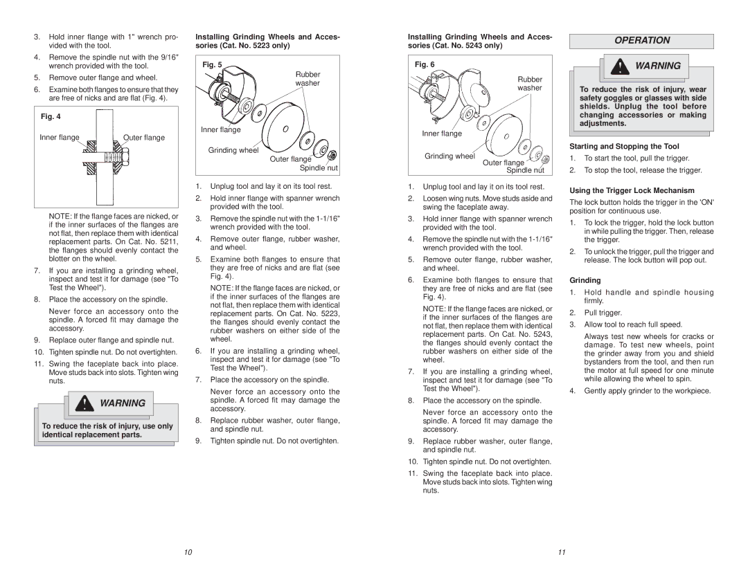
Installing Grinding Wheels and Acces- sories (Cat. No. 5223 only)
Installing Grinding Wheels and Acces- sories (Cat. No. 5243 only)
OPERATION
| wrench provided with the tool. |
5. | Remove outer flange and wheel. |
6. | Examine both flanges to ensure that they |
| are free of nicks and are flat (Fig. 4). |
Fig. 4
Inner flange | Outer flange |
Fig. 5
Rubber washer
Inner flange
Grinding wheel
Outer flange
Spindle nut
Fig. 6
Inner flange
Grinding wheel
Rubber washer
Outer flange
Spindle nut
![]() WARNING
WARNING
To reduce the risk of injury, wear safety goggles or glasses with side shields. Unplug the tool before changing accessories or making adjustments.
Starting and Stopping the Tool
1.To start the tool, pull the trigger.
2.To stop the tool, release the trigger.
NOTE: If the flange faces are nicked, or if the inner surfaces of the flanges are not flat, then replace them with identical replacement parts. On Cat. No. 5211, the flanges should evenly contact the blotter on the wheel.
7.If you are installing a grinding wheel, inspect and test it for damage (see "To Test the Wheel").
8.Place the accessory on the spindle.
Never force an accessory onto the spindle. A forced fit may damage the accessory.
9.Replace outer flange and spindle nut.
10.Tighten spindle nut. Do not overtighten.
11.Swing the faceplate back into place. Move studs back into slots. Tighten wing nuts.
![]() WARNING
WARNING
To reduce the risk of injury, use only identical replacement parts.
1.Unplug tool and lay it on its tool rest.
2.Hold inner flange with spanner wrench provided with the tool.
3.Remove the spindle nut with the
4.Remove outer flange, rubber washer, and wheel.
5.Examine both flanges to ensure that they are free of nicks and are flat (see Fig. 4).
NOTE: If the flange faces are nicked, or if the inner surfaces of the flanges are not flat, then replace them with identical replacement parts. On Cat. No. 5223, the flanges should evenly contact the rubber washers on either side of the wheel.
6.If you are installing a grinding wheel, inspect and test it for damage (see "To Test the Wheel").
7.Place the accessory on the spindle.
Never force an accessory onto the spindle. A forced fit may damage the accessory.
8.Replace rubber washer, outer flange, and spindle nut.
9.Tighten spindle nut. Do not overtighten.
1.Unplug tool and lay it on its tool rest.
2.Loosen wing nuts. Move studs aside and swing the faceplate away.
3.Hold inner flange with spanner wrench provided with the tool.
4.Remove the spindle nut with the
5.Remove outer flange, rubber washer, and wheel.
6.Examine both flanges to ensure that they are free of nicks and are flat (see Fig. 4).
NOTE: If the flange faces are nicked, or if the inner surfaces of the flanges are not flat, then replace them with identical replacement parts. On Cat. No. 5243, the flanges should evenly contact the rubber washers on either side of the wheel.
7.If you are installing a grinding wheel, inspect and test it for damage (see "To Test the Wheel").
8.Place the accessory on the spindle.
Never force an accessory onto the spindle. A forced fit may damage the accessory.
9.Replace rubber washer, outer flange, and spindle nut.
10.Tighten spindle nut. Do not overtighten.
11.Swing the faceplate back into place. Move studs back into slots. Tighten wing nuts.
Using the Trigger Lock Mechanism
The lock button holds the trigger in the 'ON' position for continuous use.
1.To lock the trigger, hold the lock button in while pulling the trigger. Then, release the trigger.
2.To unlock the trigger, pull the trigger and release. The lock button will pop out.
Grinding
1.Hold handle and spindle housing firmly.
2.Pull trigger.
3.Allow tool to reach full speed.
Always test new wheels for cracks or damage. To test new wheels, point the grinder away from you and shield bystanders from the tool, and then run the motor at full speed for one minute while allowing the wheel to spin.
4.Gently apply grinder to the workpiece.
10 | 11 |