BULLETIN NO. 54-43-0040 Jan. 2009

PAGE 2 OF 2

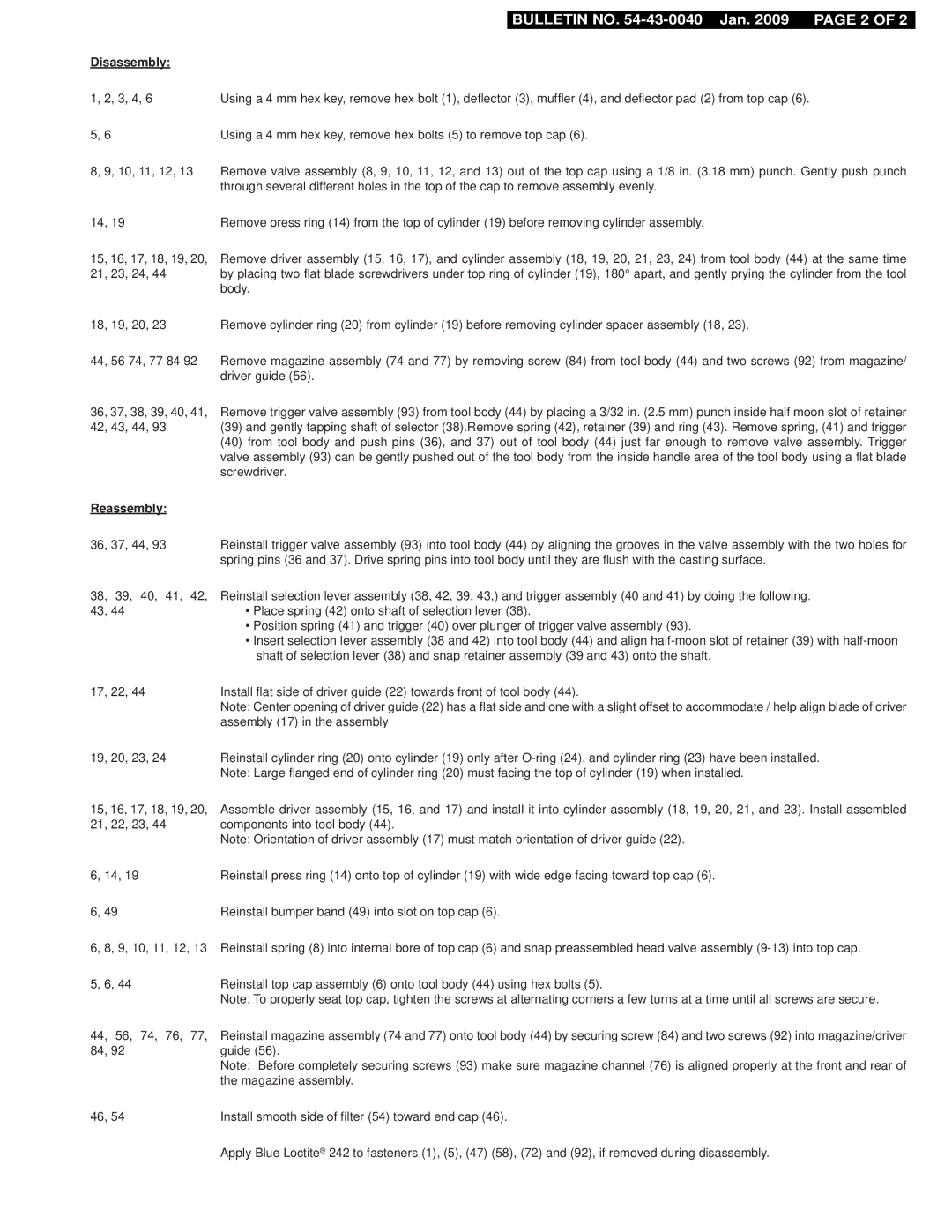
Disassembly:


1, 2, 3, 4, 6

Using a 4 mm hex key, remove hex bolt (1), deflector (3), muffler (4), and deflector pad (2) from top cap (6).


5, 6

Using a 4 mm hex key, remove hex bolts (5) to remove top cap (6).


8, 9, 10, 11, 12, 13

Remove valve assembly (8, 9, 10, 11, 12, and 13) out of the top cap using a 1/8 in. (3.18 mm) punch. Gently push punch


through several different holes in the top of the cap to remove assembly evenly.


14, 19

Remove press ring (14) from the top of cylinder (19) before removing cylinder assembly.


15, 16, 17, 18, 19, 20,

Remove driver assembly (15, 16, 17), and cylinder assembly (18, 19, 20, 21, 23, 24) from tool body (44) at the same time

21, 23, 24, 44

by placing two flat blade screwdrivers under top ring of cylinder (19), 180° apart, and gently prying the cylinder from the tool


body.


18, 19, 20, 23

Remove cylinder ring (20) from cylinder (19) before removing cylinder spacer assembly (18, 23).


44, 56 74, 77 84 92

Remove magazine assembly (74 and 77) by removing screw (84) from tool body (44) and two screws (92) from magazine/


driver guide (56).


36, 37, 38, 39, 40, 41,

Remove trigger valve assembly (93) from tool body (44) by placing a 3/32 in. (2.5 mm) punch inside half moon slot of retainer

42, 43, 44, 93

(39) and gently tapping shaft of selector (38).Remove spring (42), retainer (39) and ring (43). Remove spring, (41) and trigger


(40) from tool body and push pins (36), and 37) out of tool body (44) just far enough to remove valve assembly. Trigger


valve assembly (93) can be gently pushed out of the tool body from the inside handle area of the tool body using a flat blade


screwdriver.


Reassembly:


36, 37, 44, 93

Reinstall trigger valve assembly (93) into tool body (44) by aligning the grooves in the valve assembly with the two holes for


spring pins (36 and 37). Drive spring pins into tool body until they are flush with the casting surface.


38, 39, 40, 41, 42,

Reinstall selection lever assembly (38, 42, 39, 43,) and trigger assembly (40 and 41) by doing the following.


43, 44

• Place spring (42) onto shaft of selection lever (38).


Position spring (41) and trigger (40) over plunger of trigger valve assembly (93).

Insert selection lever assembly (38 and 42) into tool body (44) and align half-moon slot of retainer (39) with half-moon shaft of selection lever (38) and snap retainer assembly (39 and 43) onto the shaft.

17, 22, 44

Install flat side of driver guide (22) towards front of tool body (44).


Note: Center opening of driver guide (22) has a flat side and one with a slight offset to accommodate / help align blade of driver


assembly (17) in the assembly

19, 20, 23, 24

Reinstall cylinder ring (20) onto cylinder (19) only after O-ring (24), and cylinder ring (23) have been installed.


Note: Large flanged end of cylinder ring (20) must facing the top of cylinder (19) when installed.

15, 16, 17, 18, 19, 20,

Assemble driver assembly (15, 16, and 17) and install it into cylinder assembly (18, 19, 20, 21, and 23). Install assembled

21, 22, 23, 44

components into tool body (44).


Note: Orientation of driver assembly (17) must match orientation of driver guide (22).

6, 14, 19

Reinstall press ring (14) onto top of cylinder (19) with wide edge facing toward top cap (6).

6, 49

Reinstall bumper band (49) into slot on top cap (6).

6, 8, 9, 10, 11, 12, 13

Reinstall spring (8) into internal bore of top cap (6) and snap preassembled head valve assembly (9-13) into top cap.

5, 6, 44

Reinstall top cap assembly (6) onto tool body (44) using hex bolts (5).


Note: To properly seat top cap, tighten the screws at alternating corners a few turns at a time until all screws are secure.

44, 56, 74, 76, 77,

Reinstall magazine assembly (74 and 77) onto tool body (44) by securing screw (84) and two screws (92) into magazine/driver

84, 92

guide (56).


Note: Before completely securing screws (93) make sure magazine channel (76) is aligned properly at the front and rear of


the magazine assembly.

46, 54

Install smooth side of filter (54) toward end cap (46).


Apply Blue Loctite® 242 to fasteners (1), (5), (47) (58), (72) and (92), if removed during disassembly.

Page 3
Image 3
Milwaukee 54-43-0040 manual Disassembly, Reassembly

54-43-0040 specifications

The Milwaukee 54-43-0040 is a cutting-edge tool accessory designed to enhance your toolbox with efficiency and versatility. This specific model is part of Milwaukee’s robust line of high-performance products, providing users with innovative solutions for a wide array of applications.

One of the standout features of the Milwaukee 54-43-0040 is its advanced construction. Made with durable materials, the accessory is engineered to withstand rigorous use in demanding environments. This ensures a long lifespan, making it a reliable choice for both professionals and DIY enthusiasts. The accessory is designed to operate seamlessly with various Milwaukee power tools, delivering exceptional compatibility and ease of use.

In terms of technology, the Milwaukee 54-43-0040 showcases an ergonomic design that promotes user comfort during extended work sessions. The grip is strategically designed to minimize fatigue, enabling users to maintain efficiency without sacrificing comfort. Additionally, Milwaukee integrates Smart Technology in this model, which optimizes performance and enhances precision.

The 54-43-0040 is engineered to improve productivity. Whether it's for drilling, cutting, or fastening, this tool accessory provides users the flexibility to tackle diverse tasks with confidence. Its compatibility with various attachments allows for rapid changes, reducing downtime and streamlining operations.

The safety features of the Milwaukee 54-43-0040 do not go unnoticed either. The design includes protective elements that ensure secure operation, reducing the risk of accidents during use. For professionals working in high-stakes environments, these safety considerations are critical.

Furthermore, Milwaukee's commitment to sustainability is reflected in the production of the 54-43-0040. The company emphasizes environmentally responsible manufacturing processes, making it an ideal choice for those conscious of their ecological footprint.

In summary, the Milwaukee 54-43-0040 stands out as a state-of-the-art accessory that combines durability, ergonomic design, advanced technology, and safety features. Whether in a professional setting or for personal projects, this tool accessory enhances productivity and efficiency, making it an indispensable addition to any toolbox. Milwaukee continues to lead the way in innovation, and the 54-43-0040 is a testament to their commitment to quality and performance in the tool industry.