Servicing the Clutch Mechanism-
Torque Value for the Clutch Mechanism Retaining Nut (fig. no. 3).
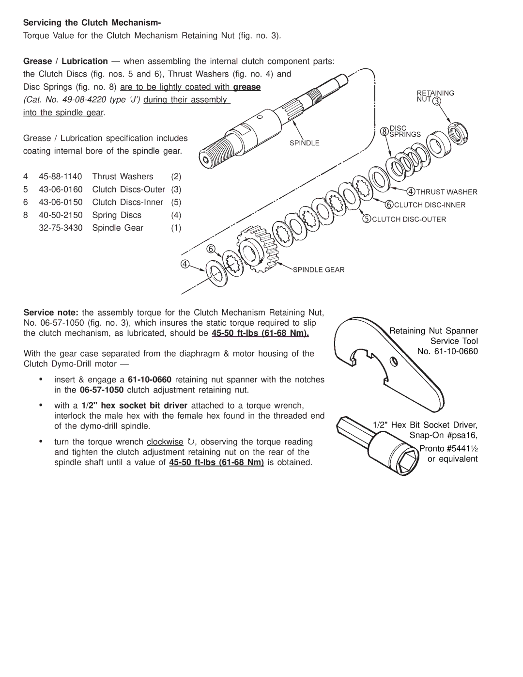
Grease / Lubrication — when assembling the internal clutch component parts: the Clutch Discs (fig. nos. 5 and 6), Thrust Washers (fig. no. 4) and
Disc Springs (fig. no. 8) are to be lightly coated with grease
(Cat. No. 49-08-4220 type ‘J’) during their assembly
into the spindle gear.
Grease / Lubrication specification includes coating internal bore of the spindle gear.
4 | Thrust Washers | (2) | |
5 | Clutch | (3) | |
6 | Clutch | (5) | |
8 | Spring Discs | (4) | |
| Spindle Gear | (1) |
Service note: the assembly torque for the Clutch Mechanism Retaining Nut, No.
With the gear case separated from the diaphragm & motor housing of the Clutch
•insert & engage a
•with a 1/2" hex socket bit driver attached to a torque wrench, interlock the male hex with the female hex found in the threaded end of the
•turn the torque wrench clockwise 3, observing the torque reading and tighten the clutch adjustment retaining nut on the rear of the spindle shaft until a value of
Retaining Nut Spanner
Service Tool
No.
1/2" Hex Bit Socket Driver,
Pronto #5441½
or equivalent