WIRING INSTRUCTIONS
TITLECORDLESS IMPACT WRENCH
MILWAUKEE ELECTRIC TOOL CORP. 13135 WEST LISBON RD. BROOKFIELD, WIS. | DATE |
Mar. 2010
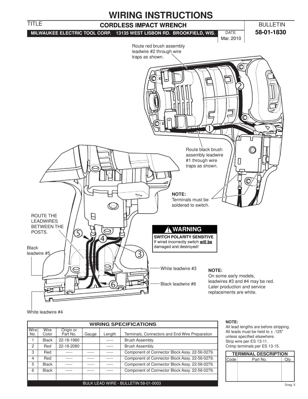
Route red brush assembly leadwire #2 through wire traps as shown.
Route black brush assembly leadwire #1 through wire traps as shown.
NOTE:
Terminals must be soldered to switch.
ROUTE THE
LEADWIRES
BETWEEN THE! WARNING POSTS.
SWITCH POLARITY SENSITIVE
If wired incorrectly switch will be
Blackdamaged and destroyed! leadwire #5
BULLETIN
58-01-1830
White leadwire #3
Black leadwire #6
NOTE:
On some early models, leadwires #3 and #4 may be red. Later production and service replacements are white.
White leadwire #4
WIRING SPECIFICATIONS
Wire | Wire | Origin or | Gauge | Length | Terminals, Connectors and End Wire Preparation |
No. | Color | Part No. | |||
1 | Black |
| Brush Assembly. | ||
|
|
|
|
|
|
2 | Red |
| Brush Assembly. | ||
3 | Red | Component of Connector Block Assy. | |||
|
|
|
|
|
|
4 | Red | Component of Connector Block Assy. | |||
5 | Black | Component of Connector Block Assy. | |||
|
|
|
|
|
|
6 | Black | Component of Connector Block Assy. | |||
|
|
|
|
|
|
BULK LEAD WIRE - BULLETIN 58-01-0003
NOTE:
All lead lengths are before stripping. All leads must be held to ± .125" unless specified elsewhere.
Strip wire per ES
TERMINAL DESCRIPTION
Code | Part No. | Qty. |
|
|
|
Drwg. 5