FUNCTIONAL DESCRIPTION
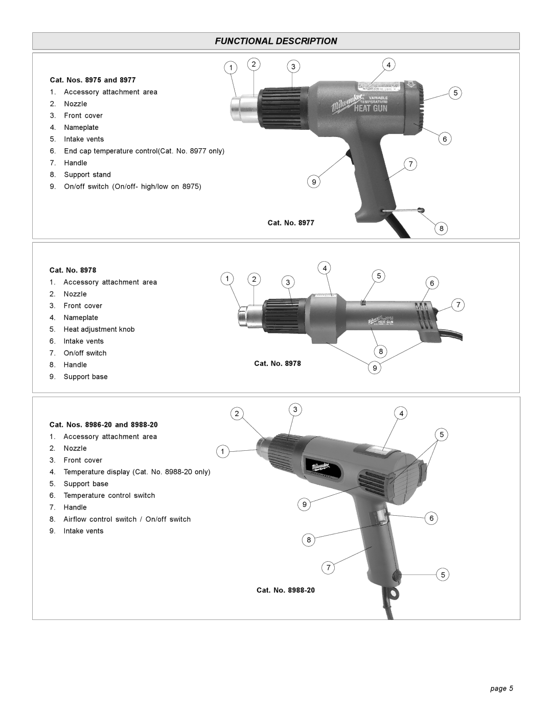
Cat. Nos. 8975 and 8977
1.Accessory attachment area
2.Nozzle
3.Front cover
4.Nameplate
5.Intake vents
6.End cap temperature control(Cat. No. 8977 only)
7.Handle
8.Support stand
9.On/off switch (On/off- high/low on 8975)
1 | 2 | 3 | 4 |
|
|
5
6
7
9
Cat. No. 8977
8
Cat. No. 8978 |
|
|
| 4 | |
1. Accessory attachment area | 1 | 2 | 3 | 5 | |
6 | |||||
|
|
2.Nozzle
3. Front cover | 7 |
4.Nameplate
5.Heat adjustment knob
6.Intake vents
7. | On/off switch |
| 8 |
8. | Handle | Cat. No. 8978 | 9 |
|
|
|
9.Support base
|
| 2 | 3 | 4 |
|
|
| ||
Cat. Nos. |
|
|
| |
1. | Accessory attachment area |
|
| 5 |
2. | Nozzle | 1 |
|
|
|
|
|
| |
3.Front cover
4.Temperature display (Cat. No.
5.Support base
6.Temperature control switch
7. | Handle | 9 |
| ||
8. | Airflow control switch / On/off switch | 6 |
9.Intake vents
8
7
5
Cat. No.
page 5
