|
|
|
|
|
| ||||
|
|
|
|
|
|
| |||
Positions |
| Torque | Torque |
| Torque | ||||
1 - 5 | 0 - 17 in. lbs. | 0 - 17 in. lbs. | 0 - 17 in. lbs. | ||||||
|
|
|
|
|
|
|
|
|
|
6 - 10 | 21 | - 38 | in. lbs. | 21 | - 38 | in. lbs. | 21 | - 38 | in. lbs. |
|
|
|
|
|
|
|
|
|
|
11 - 15 | 42 | - 60 | in. lbs. | 42 | - 60 | in. lbs. | 42 | - 60 | in. lbs. |
|
|
|
|
|
|
|
|
|
|
16 - 20 | 65 | - 85 | in. lbs. | 65 | - 85 | in. lbs. | 65 | - 85 | in. lbs. |
|
|
|
|
|
|
|
|
|
|
Drill | 460 in. lbs. | 350 in. lbs | 495 in. lbs. | ||||||
Low | |||||||||
High | 160 in. lbs. | 120 in. lbs. | 175 in. lbs. | ||||||
|
|
|
|
|
|
|
|
|
|
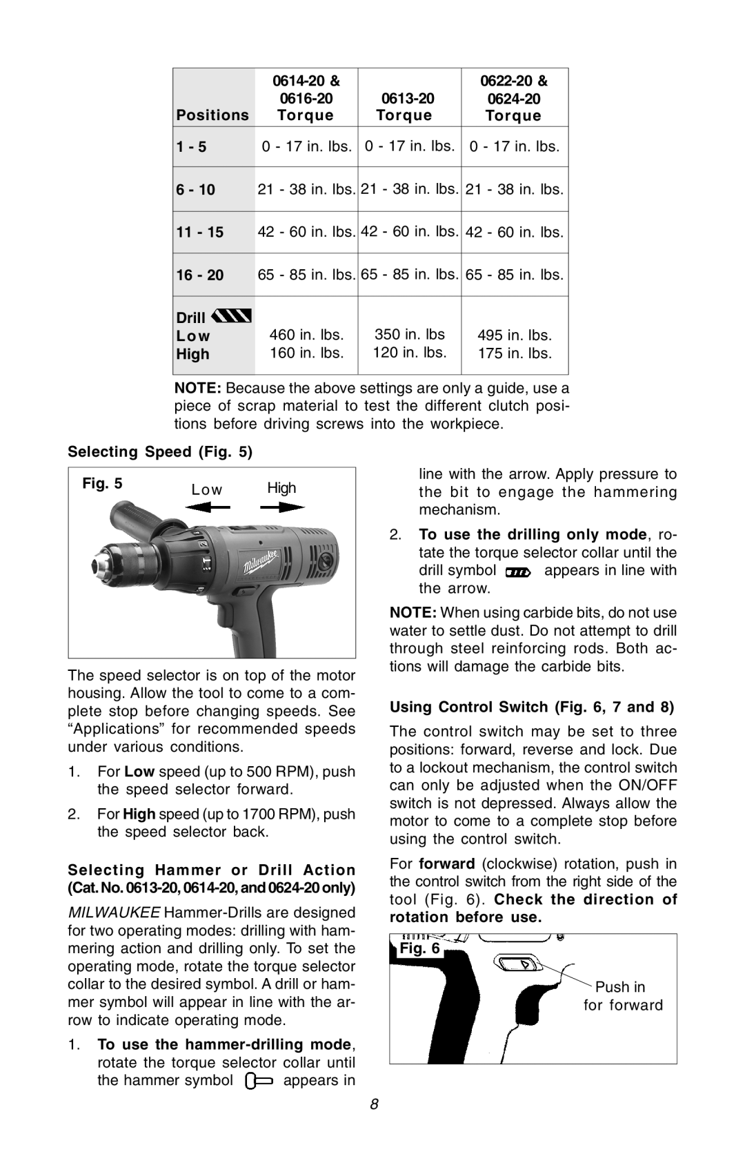
NOTE: Because the above settings are only a guide, use a piece of scrap material to test the different clutch posi- tions before driving screws into the workpiece.
Selecting Speed (Fig. 5)
Fig. 5 | Low | High |
|
The speed selector is on top of the motor housing. Allow the tool to come to a com- plete stop before changing speeds. See “Applications” for recommended speeds under various conditions.
1.For Low speed (up to 500 RPM), push the speed selector forward.
2.For High speed (up to 1700 RPM), push the speed selector back.
Selecting Hammer or Drill Action (Cat. No.
MILWAUKEE
1.To use the
the hammer symbol ![]() appears in
appears in
line with the arrow. Apply pressure to the bit to engage the hammering mechanism.
2.To use the drilling only mode, ro- tate the torque selector collar until the
drill symbol ![]() appears in line with the arrow.
appears in line with the arrow.
NOTE: When using carbide bits, do not use water to settle dust. Do not attempt to drill through steel reinforcing rods. Both ac- tions will damage the carbide bits.
Using Control Switch (Fig. 6, 7 and 8)
The control switch may be set to three positions: forward, reverse and lock. Due to a lockout mechanism, the control switch can only be adjusted when the ON/OFF switch is not depressed. Always allow the motor to come to a complete stop before using the control switch.
For forward (clockwise) rotation, push in the control switch from the right side of the tool (Fig. 6). Check the direction of rotation before use.
Fig. 6
Push in for forward
8
