465. NetCommand IR Control (837 Series)

IR Emitter Placement

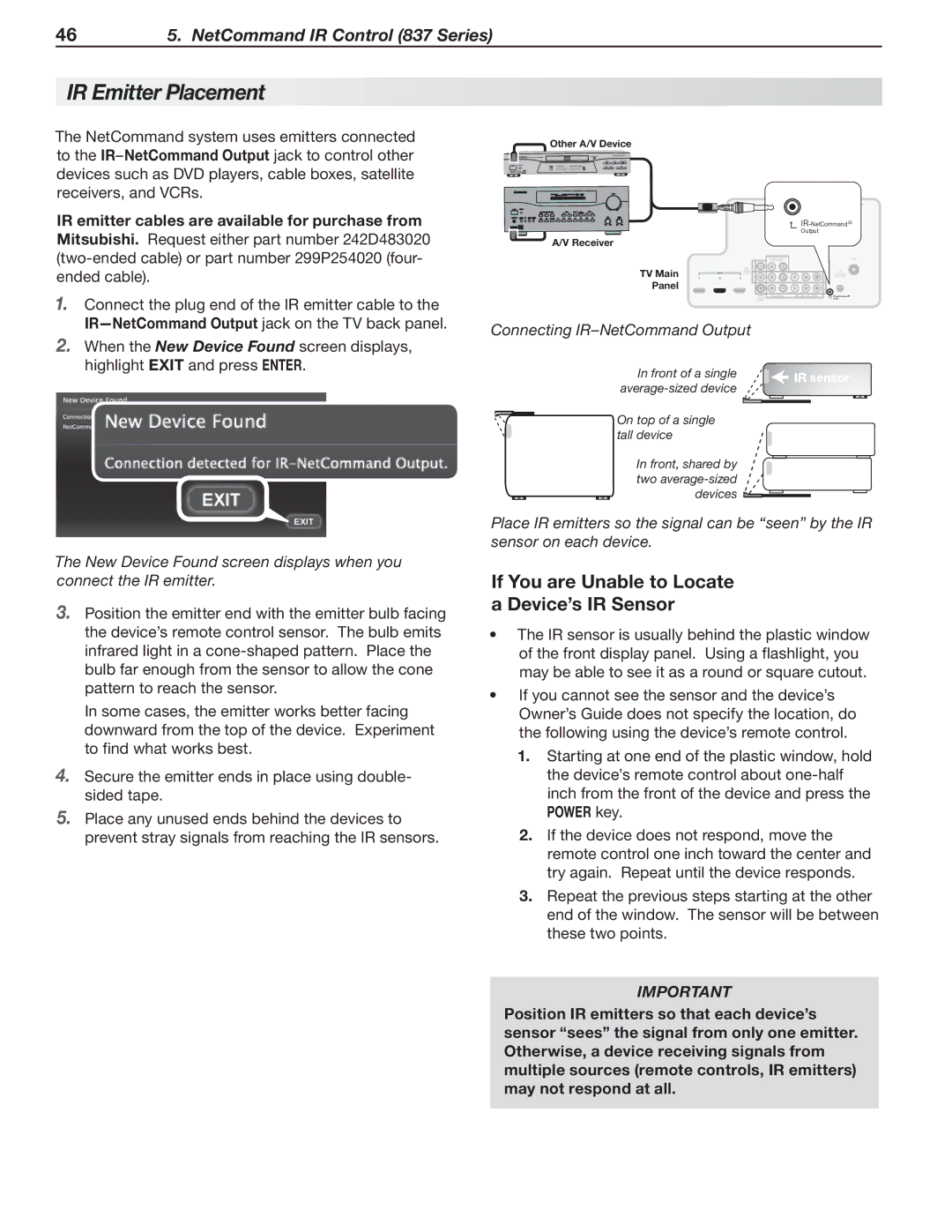
The NetCommand system uses emitters connected to the IRNetCommand Output jack to control other devices such as DVD players, cable boxes, satellite receivers, and VCRs.

IR emitter cables are available for purchase from Mitsubishi. Request either part number 242D483020 (two-ended cable) or part number 299P254020 (four-

Other A/V Device

A/V Receiver

IR-NetCommand R Output

ended cable).

1.Connect the plug end of the IR emitter cable to the IR—NetCommand Output jack on the TV back panel.

2.When the New Device Found screen displays, highlight EXIT and press ENTER.

The New Device Found screen displays when you connect the IR emitter.

3.Position the emitter end with the emitter bulb facing the device’s remote control sensor. The bulb emits infrared light in a cone-shaped pattern. Place the bulb far enough from the sensor to allow the cone pattern to reach the sensor.

In some cases, the emitter works better facing downward from the top of the device. Experiment to find what works best.

4.Secure the emitter ends in place using double- sided tape.

5.Place any unused ends behind the devices to prevent stray signals from reaching the IR sensors.


DVI/PC INPUT


ANT


R AUDIO L


TV Main


AVR

L


AUDIO

R


EMITTER


HDMI


Y/ VIDEO

Pb

Pr 2

3D


OUTPUT


GLASSES


Panel

12

3


INPUT


Y/ VIDEO

Pb

INPUT 1


Pr


DIGITAL

R AUDIO L

(480i / 480p / 720p / 1080i)

IR-NetCommand


AUDIO


Output


OUTPUT


Connecting IR–NetCommand Output


In front of a single


IR sensor


average-sized device


IR sensor

On top of a single


tall device


IR sensor


IR sensor


In front, shared by


IR sensor


two average-sized


devices


Place IR emitters so the signal can be “seen” by the IR sensor on each device.

If You are Unable to Locate a Device’s IR Sensor

The IR sensor is usually behind the plastic window of the front display panel. Using a flashlight, you may be able to see it as a round or square cutout.

If you cannot see the sensor and the device’s Owner’s Guide does not specify the location, do the following using the device’s remote control.

1.Starting at one end of the plastic window, hold the device’s remote control about one-half inch from the front of the device and press the POWER key.

2.If the device does not respond, move the remote control one inch toward the center and try again. Repeat until the device responds.

3.Repeat the previous steps starting at the other end of the window. The sensor will be between these two points.

IMPORTANT

Position IR emitters so that each device’s sensor “sees” the signal from only one emitter. Otherwise, a device receiving signals from multiple sources (remote controls, IR emitters) may not respond at all.

Page 46
Image 46
Mitsubishi Electronics 837 SERIES, 737 SERIES manual IR Emitter Placement, If You are Unable to Locate a Device’s IR Sensor

837 SERIES, 737 SERIES specifications

Mitsubishi Electronics has established itself as a key player in the world of automation and control with its innovative series of programmable logic controllers (PLCs), notably the 737 Series and 837 Series. These PLCs are designed to meet the rigorous demands of modern industrial automation, providing a blend of versatility, efficiency, and advanced technology.

The Mitsubishi 737 Series PLC is renowned for its compact design and high processing power. A significant feature of this series is its modular architecture, allowing users to expand and customize their systems according to specific application needs. The 737 Series is equipped with advanced I/O options, offering diverse configurations that support both digital and analog inputs and outputs. This multiplicity equips operators with remarkable flexibility for various automation processes, from simple machine control to complex manufacturing systems.

On the other hand, the 837 Series separates itself through an extensive range of built-in functionalities and connectivity options. One critical feature of the 837 Series is its high-speed processing capabilities. The controller effectively executes ladder programming and structured text, allowing engineers to develop complex control algorithms seamlessly. Additionally, the 837 Series supports Ethernet and other communication protocols, enabling easy integration in networked environments. This connectivity enhances real-time data sharing and remote monitoring, ensuring improved operational efficiency.

Both series utilize Mitsubishi Electronics' proprietary technologies, such as the MELSEC system, which promotes high reliability and ease of use. The user-friendly programming environment supports both graphical and textual programming, accommodating developers with varying skill levels. Moreover, Mitsubishi’s Cyber Security features ensure that the systems remain secure against potential threats in an increasingly connected industrial landscape.

In terms of energy efficiency and sustainability, both the 737 and 837 Series PLCs incorporate advanced power management capabilities, reducing energy consumption while maintaining optimal performance. Their robust build quality also ensures longevity in harsh industrial conditions, securing investments and enhancing overall operational reliability.

In conclusion, the Mitsubishi 737 Series and 837 Series PLCs represent the forefront of automation technology, providing essential features, cutting-edge processing power, and unmatched flexibility. Their integration into industrial applications continues to propel efficiency and innovation across various sectors, solidifying Mitsubishi Electronics’ reputation as a leader in automation solutions.