Manuals
/
Mitsubishi Electronics
/
Computer Equipment
/
Projector
Mitsubishi Electronics
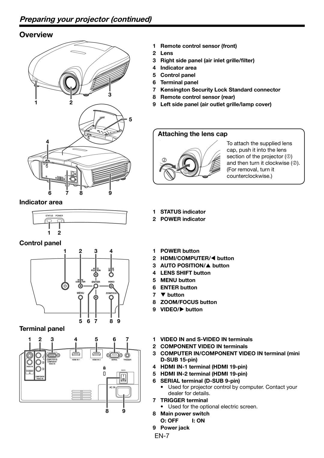
HC6800 Preparing your projector continued, Overview, Indicator area, O Off
Models:
HC6800
1
7
47
47
Download
47 pages
34.22 Kb
4
5
6
7
8
9
10
11
Troubleshooting
Specs
Install
SIGNAL menu
Password
Indicator area
Checking accessories
Connectors
Adjustment feet
Setting up your projector
Page 7
Image 7
Page 6
Page 8
Page 7
Image 7
Page 6
Page 8
Contents
LCD PROJECTOR
MODEL
HC6800
HC6800
CAUTION TO REDUCE THE RISK OF ELECTRIC
SHOCK, DO NOT REMOVE COVER OR BACK NO USER-SERVICEABLE PARTS INSIDE
REFER SERVICING TO QUALIFIED SERVICE PERSONNEL
THE PROJECTOR IS IN THE POWER ON MODE
Trademark, Registered trademark
Contents
EN-4
Important safeguards
Do not unplug the power cord during operation
Important safeguards continued
Do not keep using the damaged projector
Do not look into the lens when it is operating
Inserting the batteries into the remote control
Checking accessories
Preparing your projector
Attaching the lens cap
Indicator area
Preparing your projector continued
Overview
Adjustment feet
Remote control
Using the picture quality adjusting buttons
Bottom side
Front of projector
Using the remote control
Operational range of the remote control
Reception angle
Screen size and projection distance
Setting up your projector
Setting up the screen
When the aspect ratio of the screen is
When the aspect ratio of the image is
Setting up your projector continued
When the aspect ratio of the screen is 2.351 CinemaScope
Screen size and projection distance continued
Correcting skewed or distorted image
Adjusting the position of the projected image
When fine streaks are seen on projected images
When projected images are distorted to a trapezoid
TRIGGER terminal
Front projection, ceiling mounting
Rear projection
Preparation
A. Connecting the projector to video equipment
Viewing video images
Basic home theater system connection
When a TV tuner or VCR is connected
Connecting to a video player, etc
Connecting to a DVD player or HDTV decoder
Viewing video images continued
EN-16
Connecting to video equipment having a HDMI terminal
Connection for video equipment having an HDMI terminal
EN-17
B. Plugging in the power cord
EN-18
C. Projecting images
EN-19
To stop projecting
EN-20
Setting the aspect ratio
With the remote control
How to change the settings
With the FEATURE menu See page 26 for menu setting
About DDC
A. Connecting the projector to a computer
B. Plugging the power cord
Viewing computer images
Viewing computer images continued
Example of the setting procedure for external output
When connecting to a notebook computer
Setting of the resolution
AUTO POSITION button
EN-25
Menu operation
1. IMAGE menu
How to set the menus
Available settings in the menus
Menu operation continued
EN-27
2. INSTALLATION menu
EN-28
3. FEATURE menu
EN-29
4. SIGNAL menu
5. USER menu
6. INFORMATION menu
AV memory
To store the settings
To enable the stored image quality settings
To sharpen or soften the projected image SHARPNESS
Adjusting projected images
To adjust the brightness CONTRAST and BRIGHTNESS
To adjust the color COLOR and TINT
About color temperature
Adjusting projected images continued
To adjust the tone of white COLOR TEMP
To adjust the tone of white To customize the color temperature
TRNR temporal recursive noise reduction
To adjust the ratio of change in brightness GAMMA MODE
Noise reduction
To enable the stored gamma mode
To adjust the horizontal position
How to adjust the image supplied from the computer using the menu
LPF Progressive filter
Simple method to adjust the image position
To cancel the password function
Advanced features
Password function
To enable the password function
Replacing the lamp
Interval of lamp replacement
To replace the lamp
Replacing the lamp continued
Reset of the lamp operation time
EN-38
When removing the lamp from the ceiling-mounted projector
For the air-filter white
Cleaning of the projector and the ventilation slots
Cleaning of the lens
EN-39
EN-40
Troubleshooting
Problem
Solution
No image appears on the screen. continued
Troubleshooting continued
Images are not displayed correctly
Others
Images are not displayed correctly. continued
Normal condition
Indicators
Abnormal condition
Dimension drawings unit mm
Specifications
Specification of RGB signals in each computer mode of the projector
Specifications continued
EN-45
Replacement part option/not included in the box
Connectors
EN-46
1 Zusho Baba, Nagaokakyo-City, Kyoto Japan
MITSUBISHI ELECTRIC CORPORATION
Top
Page
Image
Contents