2 |
| 3 | ➤ |
| 3/8" (9.5mm)DIA. DRILLED HOLE | ||
|
|
| AGUJERO PERFORADO |
|
|
| DIAMETRO 3/8" (9.5mm) |
| CUTOUT |
| NOTE: IT IS RECOMMENDED |
| LINE |
| |
|
| TO USE A 3/8" (9.5mm) WIDE, 8 TO 10 | |
|
|
| |
| LÍNEA DE |
| |
1/4" | CORTE |
| NOTA: SE RECOMIENDA USAR CUCHILLA |
|
| PARA SIERRA CALADORA DE ANCHO 3/8" | |
(6.4mm) |
|
| (9.5mm), 8 A 10 DIENTES POR PULGADA (25.4mm) |
➤ |
|
|
|
➤ | ➤ |
|
|
| ➤ |
|
|
|
|
| ➤ |
| RIM OUTLINE |
| CUTOUT |
| LÍNEA DE |
| LINE |
|
|
| |
| BORDE |
| LÍNEA DE |
|
|
| CORTE |
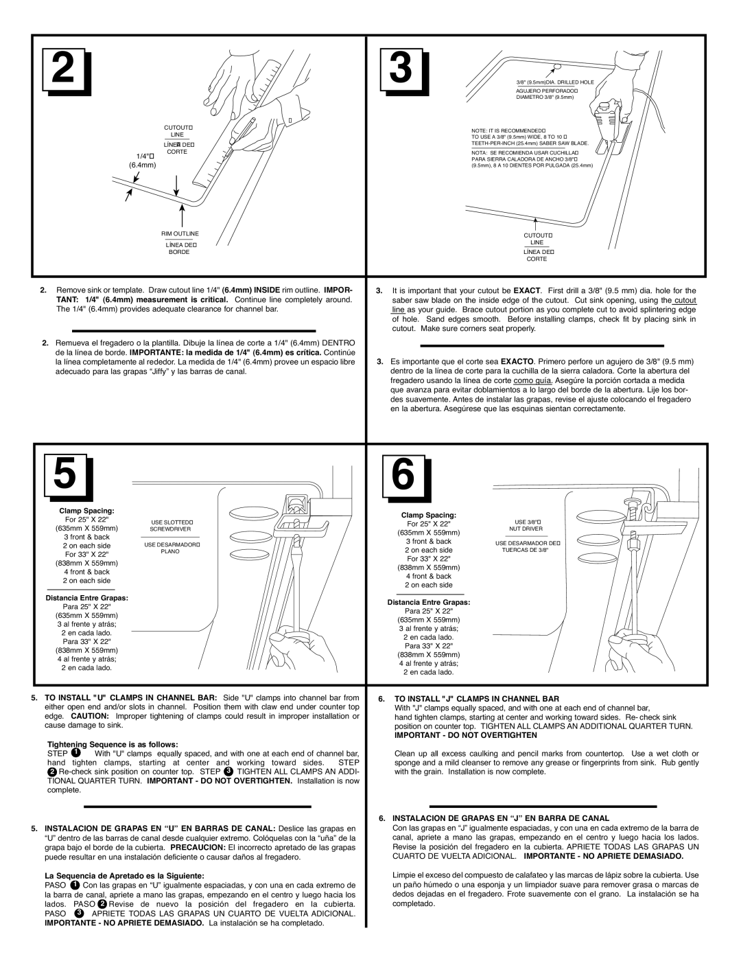
2.Remove sink or template. Draw cutout line 1/4" (6.4mm) INSIDE rim outline. IMPOR- 3. It is important that your cutout be EXACT. First drill a 3/8" (9.5 mm) dia. hole for the
TANT: 1/4" (6.4mm) measurement is critical. Continue line completely around. | saber saw blade on the inside edge of the cutout. Cut sink opening, using the cutout | ||
The 1/4" (6.4mm) provides adequate clearance for channel bar. | line as your guide. Brace cutout portion as you complete cut to avoid splintering edge | ||
|
|
| of hole. Sand edges smooth. Before installing clamps, check fit by placing sink in |
|
|
| cutout. Make sure corners seat properly. |
2.Remueva el fregadero o la plantilla. Dibuje la línea de corte a 1/4" (6.4mm) DENTRO
de la línea de borde. IMPORTANTE: la medida de 1/4" (6.4mm) es crítica. Continúe | 3. Es importante que el corte sea EXACTO. Primero perfore un agujero de 3/8" (9.5 mm) |
la línea completamente al rededor. La medida de 1/4" (6.4mm) provee un espacio libre | |
adecuado para las grapas “Jiffy” y las barras de canal. | dentro de la línea de corte para la cuchilla de la sierra caladora. Corte la abertura del |
| fregadero usando la línea de corte como guía. Asegúre la porción cortada a medida |
| que avanza para evitar doblamientos a lo largo del borde de la abertura. Lije los bor- |
| des suavemente. Antes de instalar las grapas, revise el ajuste colocando el fregadero |
| en la abertura. Asegúrese que las esquinas sientan correctamente. |
5 |
| 6 |
| |
Clamp Spacing: |
| Clamp Spacing: |
| |
For 25" X 22" |
| USE 3/8" | ||
USE SLOTTED | For 25" X 22" | |||
(635mm X 559mm) | ||||
SCREWDRIVER | (635mm X 559mm) | NUT DRIVER | ||
3 front & back |
|
| ||
| 3 front & back | USE DESARMADOR DE | ||
2 on each side | USE DESARMADOR | |||
2 on each side | TUERCAS DE 3/8" | |||
For 33" X 22" | PLANO | |||
| For 33" X 22" |
| ||
(838mm X 559mm) |
|
| ||
| (838mm X 559mm) |
| ||
4 front & back |
|
| ||
| 4 front & back |
| ||
2 on each side |
|
| ||
| 2 on each side |
| ||
|
|
| ||
Distancia Entre Grapas: |
| Distancia Entre Grapas: |
| |
Para 25" X 22" |
|
| ||
| Para 25" X 22" |
| ||
(635mm X 559mm) |
|
| ||
| (635mm X 559mm) |
| ||
3 al frente y atrás; |
|
| ||
| 3 al frente y atrás; |
| ||
2 en cada lado. |
|
| ||
| 2 en cada lado. |
| ||
Para 33" X 22" |
|
| ||
| Para 33" X 22" |
| ||
(838mm X 559mm) |
|
| ||
| (838mm X 559mm) |
| ||
4 al frente y atrás; |
|
| ||
| 4 al frente y atrás; |
| ||
2 en cada lado. |
|
| ||
| 2 en cada lado. |
| ||
|
|
|
5. TO INSTALL "U" CLAMPS IN CHANNEL BAR: Side "U" clamps into channel bar from | 6. TO INSTALL "J" CLAMPS IN CHANNEL BAR | ||||||
either open end and/or slots in channel. Position them with claw end under counter top | With "J" clamps equally spaced, and with one at each end of channel bar, | ||||||
edge. | CAUTION: Improper tightening of clamps could result in improper installation or | hand tighten clamps, starting at center and working toward sides. Re- check sink | |||||
cause damage to sink. |
|
| position on counter top. TIGHTEN ALL CLAMPS AN ADDITIONAL QUARTER TURN. | ||||
Tightening Sequence is as follows: |
|
| IMPORTANT - DO NOT OVERTIGHTEN | ||||
|
|
|
|
| |||
STEP | 1 | With "U" clamps equally spaced, and with one at each end of channel bar, | Clean up all excess caulking and pencil marks from countertop. Use a wet cloth or | ||||
hand | tighten clamps, starting at center and | working toward sides. STEP | sponge and a mild cleanser to remove any grease or fingerprints from sink. Rub gently | ||||
2 | TIGHTEN ALL CLAMPS AN ADDI- | with the grain. Installation is now complete. | |||||
TIONAL QUARTER TURN. IMPORTANT - DO NOT OVERTIGHTEN. Installation is now |
|
|
| ||||
complete. |
|
|
|
|
|
| |
|
|
|
|
|
|
|
|
|
|
|
|
| 6. INSTALACION DE GRAPAS EN “J” EN BARRA DE CANAL | ||
5. INSTALACION DE GRAPAS EN “U” EN BARRAS DE CANAL: Deslice las grapas en | Con las grapas en “J” igualmente espaciadas, y con una en cada extremo de la barra de | ||||||
“U” dentro de las barras de canal desde cualquier extremo. Colóquelas con la “uña” de la | canal, apriete a mano las grapas, empezando en el centro y luego hacia los lados. | ||||||
grapa bajo el borde de la cubierta. PRECAUCION: El incorrecto apretado de las grapas | Revise la posición del fregadero en la cubierta. APRIETE TODAS LAS GRAPAS UN | ||||||
puede resultar en una instalación deficiente o causar daños al fregadero. | CUARTO DE VUELTA ADICIONAL. IMPORTANTE - NO APRIETE DEMASIADO. | ||||||
La Sequencia de Apretado es la Siguiente: |
|
| Limpie el exceso del compuesto de calafateo y las marcas de lápiz sobre la cubierta. Use | ||||
PASO | 1 | Con las grapas en “U” igualmente espaciadas, y con una en cada extremo de | un paño húmedo o una esponja y un limpiador suave para remover grasa o marcas de | ||||
la barra de canal, apriete a mano las grapas, empezando en el centro y luego hacia los | dedos dejadas en el fregadero. Frote suavemente con el grano. La instalación se ha | ||||||
lados. | PASO 2 Revise de nuevo la posición | del fregadero en la cubierta. | completado. | ||||
PASO | 3 | APRIETE TODAS LAS GRAPAS UN CUARTO DE VUELTA ADICIONAL. |
|
|
| ||
IMPORTANTE - NO APRIETE DEMASIADO. La instalación se ha completado. |
|
|
| ||||