M400BFC Balanced Flue
Operation
Before the first fire, the location of the upper refractory baffle (ceiling panel) should be checked. This part floats intentionally and may move out of place during ship- ping or installation of the fireplace. If the baffle is out of place, the resulting improper air flow will cause dirty glass and improper combustion. The baffle should be centered
Refer to the publication “How to Enjoy Your Woodburn- ing Fireplace” for starting and maintaining a wood fire.
Note that the M400BFC does not have a damper to open or close. This is a tremendous efficiency increas- ing advantage since there is no damper to potentially leave open after a fire dies down. House air will not escape up the chimney. Note also that the doors should remain closed at all times except when starting or reloading a fire.
Burn only seasoned firewood. Typically, only two or three burning logs are needed to provide efficient sup- plemental heat and a bright decorative fire. In general, fresh wood should not be loaded higher than about 2/3 the height of the firebox.
Installing Line for Gas Logs
MHSC fireplaces are designed to accept a 1/2” (13 mm) gas line for installation of an approved gas appliance. (MHSC manufactures a wide variety of gas logs for use in MHSC fireplaces.)
Be sure to have the appliance installed in accordance with building codes.
Gas connection may enter from either left or right side of the fireplace.
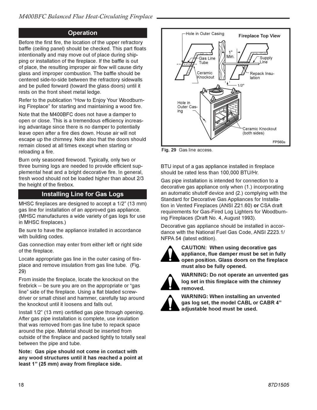
Locate appropriate gas line in the outer casing of fire- place and remove insulation from gas line tube. (Fig. 29)
From inside the fireplace, locate the knockout on the firebrick
Install 1/2” (13 mm) certified gas pipe through opening. After gas pipe installation is complete, use insulation that was removed from gas line tube to repack space around the pipe. Material should be inserted from outside of the fireplace and packed tightly to totally seal between the pipe and tube.
Note: Gas pipe should not come in contact with any wood structures until it has reached a point at least 1” (25 mm) away from fireplace side.
Hole in Outer Casing |
| Fireplace Top View |
|
| |
| 1" |
|
Gas Line | Min. | Supply |
Tube |
| Line |
Ceramic |
| Repack Insu- |
Knockout |
| lation |
|
| 1/2" |
Hole in Outer Cas- ing ![]()
Ceramic Knockout (both sides)
FP560a
Fig. 29 Gas line access.
BTU input of a gas appliance installed in fireplace should be rated less than 100,000 BTU/Hr.
Gas pipe installation is intended for connection to a decorative gas appliance only when (1.) incorporating an automatic shutoff device and (2.) complying with the Standard for Decorative Gas Appliances for Installa- tion in Vented Fireplaces (ANSI Z21.60) or CSA draft requirements for
Decorative gas appliance should be installed in accor- dance with the National Fuel Gas Code, ANSI Z223.1/ NFPA 54 (latest edition).
CAUTION: When using decorative gas appliance, flue damper must be set in fully open position. Glass doors on the fireplace must also be fully opened.
WARNING: Do not operate an unvented gas
log set in this fireplace with the chimney removed.
WARNING: When installing an unvented gas log set, the model CABL or CABR 4” adjustable hood must be used.
18 | 87D1505 |