Note:
After installation, please refer to operation, maintenance and troubleshooting sections in this manual. If your fan is packaged with a light kit or
if you wish to install a separately purchased light kit, please refer to the insert sheet titled: Light Kit Installation
7 |
|
| Standard wiring option | ||||||
|
| ||||||||
|
|
| Black |
| House |
| Fan | Black |
|
|
|
|
|
| |||||
|
|
|
|
|
|
| |||
* Attach blue wire |
|
|
|
|
|
| Blue * |
| |
only if attaching |
|
|
|
|
|
|
|
| |
White |
|
|
|
| White |
| |||
light kit with fan |
|
|
|
|
| ||||
|
| Green |
|
|
|
|
|
| |
|
|
|
|
| Green(Downrod) |
| |||
|
|
|
|
|
|
| |||
8 | Wiring option with wall speed control |
9
Secure with ![]()
Green(Bracket)
Fan Switch
Light Switch
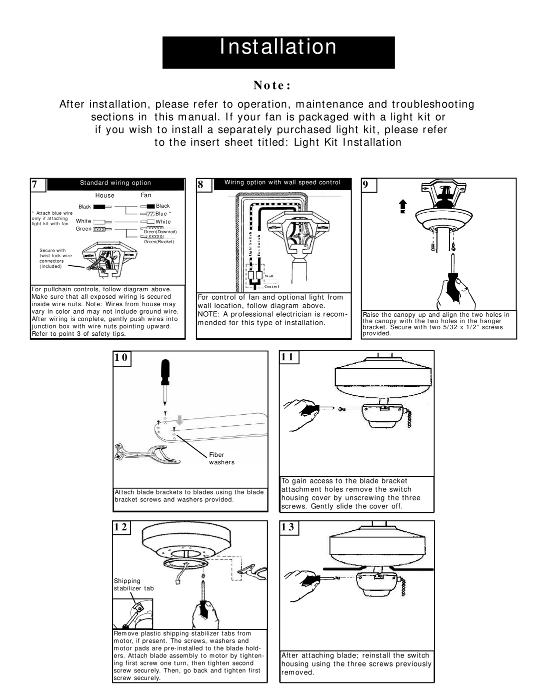
For pullchain controls, follow diagram above. |
|
| Wall |
|
|
|
|
| |||
|
| Control |
|
|
|
|
| ||||
|
|
|
| ||||||||
|
| For control of fan and optional light from |
|
|
| ||||||
Make sure that all exposed wiring is secured |
|
|
|
|
| ||||||
|
|
|
|
| |||||||
inside wire nuts. Note: Wires from house may |
|
| wall location, follow diagram above. |
|
|
| |||||
vary in color and may not include ground wire. |
|
| NOTE: A professional electrician is recom- |
| Raise the canopy up and align the two holes in |
| |||||
|
|
|
| ||||||||
After wiring is conplete, gently push wires into |
|
| mended for this type of installation. |
| the canopy with the two holes in the hanger |
| |||||
junction box with wire nuts pointing upward. |
|
|
| bracket. Secure with two 5/32 x 1/2” screws |
| ||||||
Refer to point 3 of safety tips. |
|
|
|
|
|
|
| provided. |
| ||
| 10 |
|
|
|
| 11 |
|
|
|
|
|
|
|
|
|
|
|
|
|
|
| ||
|
|
|
|
|
|
|
|
|
|
|
|
|
|
|
|
|
|
|
|
|
|
|
|
|
|
|
|
|
|
|
|
|
|
|
|
Fiber washers
|
|
|
|
|
|
|
|
| To gain access to the blade bracket |
| |||
|
|
|
|
|
|
|
|
|
| ||||
|
|
| Attach blade brackets to blades using the blade |
| attachment holes remove the switch |
| |||||||
|
|
|
|
| |||||||||
|
|
| bracket screws and washers provided. |
| housing cover by unscrewing the three |
| |||||||
|
|
|
|
|
|
|
|
| screws. Gently slide the cover off. |
| |||
|
|
|
|
|
|
|
|
|
|
|
|
|
|
|
|
| 12 |
|
|
|
|
| 13 |
|
|
|
|
|
|
|
|
|
|
|
|
|
| ||||
|
|
| Shipping |
|
|
|
|
|
|
| |||
|
|
|
|
|
|
|
|
| |||||
|
|
| stabilizer tab |
|
|
|
|
|
|
| |||
|
|
|
|
|
|
|
|
|
|
|
|
|
|
|
| Remove plastic shipping stabilizer tabs from |
|
|
|
|
|
|
| ||||
|
|
|
|
|
|
|
|
| |||||
|
|
|
|
|
|
|
|
| |||||
|
| motor, if present. The screws, washers and |
|
|
|
|
|
|
| ||||
|
| motor pads are |
|
| After attaching blade; reinstall the switch | ||||||||
|
| ers. Attach blade assembly to motor by tighten- |
|
| |||||||||
|
|
|
| ||||||||||
|
| ing first screw one turn, then tighten second |
|
| housing using the three screws previously | ||||||||
|
| screw securely. Then, go back and tighten first |
|
| removed. | ||||||||
|
| screw securely. |
|
|
|
|
|
|
| ||||
