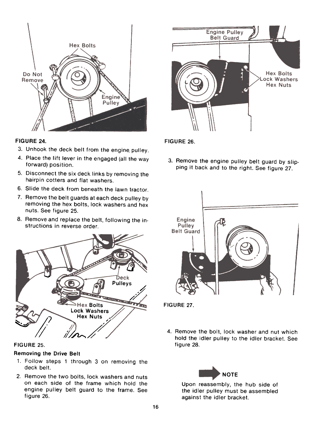
FIGURE 24.
3.Unhook the deck belt from the engine. pulley.
4.Place the lift lever in the engaged (all the way forward) position.
5.Disconnect the six deck links by removing the hairpin cotters and flat washers.
6.Slide the deck from beneath the lawn tractor.
7.Remove the belt guards at each deck pulley by removing the hex bolts, lock washers and hex nuts. See figure 25.
8.Remove and replace the belt, following the in- structions in reverse order.
FIGURE 26.
Remove the engine pulley belt guard by slip. ping it back and to the right. See figure 27.
u
..."
Pulleys ,.f
~~,f". .
Bolts
Lock Washers
Hex Nuts,
~;)7 

 f. ,;/


FIGURE 25.
Removing the Drive Belt
1.Follow steps 1 through 3 on removing the deck belt.
2.Remove the two bolts, lock washers and nuts on each side of the frame which hold the engine pulley belt guard to the frame. See figure 26.
11M""",,43.
FIGURE 27.
Remove the bolt, lock washer and nut which hold the idler pulley to the idler bracket. See figure 28.
NOTE
Upon reassembly, the hub side of the idler pulley must be assembled against the idler bracket.
16
