1 |
Introduction
Table
P14/J14, P24/J24
Pin# | Signal Name | Signal Name | Pin # |
|
|
|
|
55 | I/O | I/O | 56 |
|
|
|
|
57 | I/O | I/O | 58 |
|
|
|
|
59 | I/O | I/O | 60 |
|
|
|
|
61 | I/O | I/O | 62 |
|
|
|
|
63 | I/O | I/O | 64 |
|
|
|
|
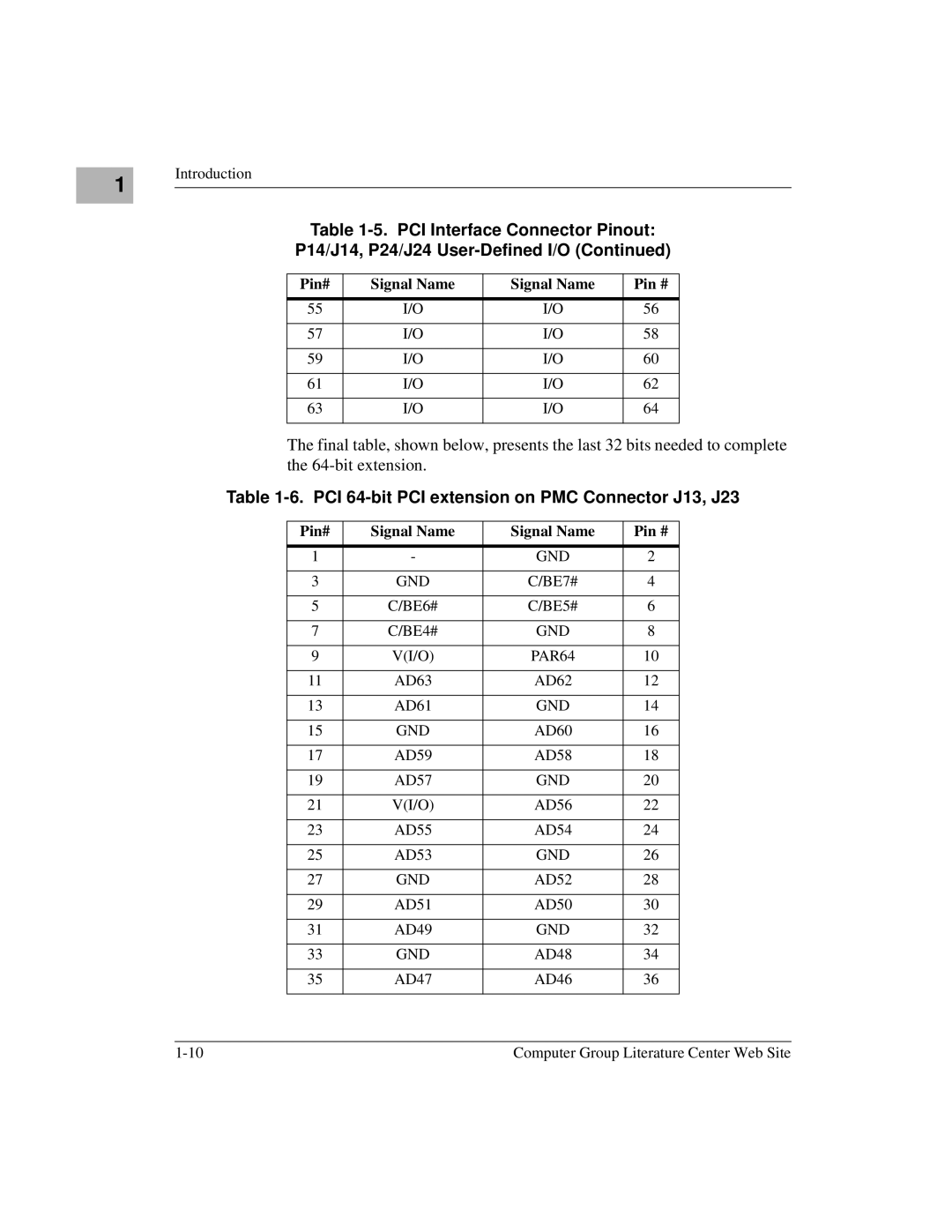
The final table, shown below, presents the last 32 bits needed to complete the
Table 1-6. PCI 64-bit PCI extension on PMC Connector J13, J23
Pin# | Signal Name | Signal Name | Pin # |
|
|
|
|
1 | - | GND | 2 |
|
|
|
|
3 | GND | C/BE7# | 4 |
|
|
|
|
5 | C/BE6# | C/BE5# | 6 |
|
|
|
|
7 | C/BE4# | GND | 8 |
|
|
|
|
9 | V(I/O) | PAR64 | 10 |
|
|
|
|
11 | AD63 | AD62 | 12 |
|
|
|
|
13 | AD61 | GND | 14 |
|
|
|
|
15 | GND | AD60 | 16 |
|
|
|
|
17 | AD59 | AD58 | 18 |
|
|
|
|
19 | AD57 | GND | 20 |
|
|
|
|
21 | V(I/O) | AD56 | 22 |
|
|
|
|
23 | AD55 | AD54 | 24 |
|
|
|
|
25 | AD53 | GND | 26 |
|
|
|
|
27 | GND | AD52 | 28 |
|
|
|
|
29 | AD51 | AD50 | 30 |
|
|
|
|
31 | AD49 | GND | 32 |
|
|
|
|
33 | GND | AD48 | 34 |
|
|
|
|
35 | AD47 | AD46 | 36 |
|
|
|
|
Computer Group Literature Center Web Site |
