Connector Pinouts
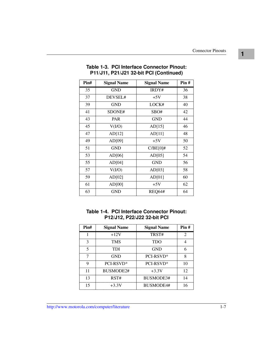
Table 1-3. PCI Interface Connector Pinout:
P11/J11, P21/J21
Pin# | Signal Name | Signal Name | Pin # |
|
|
|
|
35 | GND | IRDY# | 36 |
|
|
|
|
37 | DEVSEL# | +5V | 38 |
|
|
|
|
39 | GND | LOCK# | 40 |
|
|
|
|
41 | SDONE# | SBO# | 42 |
|
|
|
|
43 | PAR | GND | 44 |
|
|
|
|
45 | V(I/O) | AD[15] | 46 |
|
|
|
|
47 | AD[12] | AD[11] | 48 |
|
|
|
|
49 | AD[09] | +5V | 50 |
|
|
|
|
51 | GND | C/BE[0]# | 52 |
|
|
|
|
53 | AD[06] | AD[05] | 54 |
|
|
|
|
55 | AD[04] | GND | 56 |
|
|
|
|
57 | V(I/O) | AD[03] | 58 |
|
|
|
|
59 | AD[02] | AD[01] | 60 |
|
|
|
|
61 | AD[00] | +5V | 62 |
|
|
|
|
63 | GND | REQ64# | 64 |
|
|
|
|
Table 1-4. PCI Interface Connector Pinout:
P12/J12, P22/J22 32-bit PCI
Pin# | Signal Name | Signal Name | Pin # |
|
|
|
|
1 | +12V | TRST# | 2 |
|
|
|
|
3 | TMS | TDO | 4 |
|
|
|
|
5 | TDI | GND | 6 |
|
|
|
|
7 | GND | 8 | |
|
|
|
|
9 | 10 | ||
|
|
|
|
11 | BUSMODE2# | +3.3V | 12 |
|
|
|
|
13 | RST# | BUSMODE3# | 14 |
|
|
|
|
15 | +3.3V | BUSMODE4# | 16 |
|
|
|
|
1
http://www.motorola.com/computer/literature |
