Reference Manual
CPX8000 Series CPX8216/CPX8216T CompactPCI System
Page
Safety Summary
Ground the Instrument
Flammability
CE Notice European Community
FCC Class a
EMI Caution
Limited and Restricted Rights Legend
Contents
CPX8540 Carrier Card
PMC Modules
Subassembly Reference
Appendix a
List of Figures
List of Tables
Xvi
Xvii
About this Manual
Summary of Changes
Date Change
System added. See Chassis ID for CPX8216T on
Systems Supported
Model Number Description
Overview
Comments and Suggestions
Conventions Used in This Manual
Bold
Picmg Compliance
System Domains
CPX8216
System Layout
Domain a Domain B Domain A/B
CPX8216 Standard System Layout
Bus Access and Control
CPX8216T H.110
Hot Swap Controller/Bridge HSC Module
CPX8216 I/O Bus Connectivity
Hot Swap Controller
System Processor Configurations
Simplex Configuration
Active/Passive Configuration
Active/Active or Load-Sharing Configuration
Power/Fan Modules
Configurations
Peripherals
Drive Modules
CPU Complex Architecture
CPU Module
Switching Service to the Passive CPU
Alarms and LEDs
Chassis ID for CPX8216T
Board Insertion and Extraction Features
Telephony Bus
Staged Pins
BDSEL#
Hot Swap Process
Hot Swap Control Status Register CSR
Physical Connection Process
Hardware Connection Process
Software Connection Process
Software Disconnection Process
Device Drivers
Typical Insertion and Extraction Processes
Slots Description Occupied
PowerPC Hot Swappable CPU
CompactPCI Boards
Intel Hot Swappable CPU
Computer system, such as
CPX750HA
2213
USB 0 Connector J18
Connectors and Jumper Settings
USB 1 Connector J17
COM1 Connector J15
BaseT/100BaseTx Connector J8
COM1 Connector J15
DCD RXD TXD DTR GND DSR RTS CTS
PA0 PA1 PA2 PA3 PA4 PA5 PA6 PA7 PA8 PA9
Debug Connector J19
Debug Connector J19
PAPAR0 PAPAR1 PAPAR2 PAPAR3 APE Rsrv PD0 PD1 PD2 PD3
PD4 PD5 PD6 PD7 PD8 PD9
PDPAR4 PDPAR5
PDPAR0 PDPAR1
PDPAR2 PDPAR3
PDPAR6 PDPAR7
ABB
Sreset Qack
Hreset Cputdo
Tclkout MPUBG-0
Dram Mezzanine Connector J10
Dram Mezzanine Connector J10
+5V
RDL58 RDL59
RDL52 RDL53 RDL54 RDL55
RDL56 RDL57
RDL60 RDL61
RDU34 RDU35
RDU30 RDU31
RDU32 RDU33
RDU36 RDU37
GND DATA3 DATA4 DATA5 DATA6 DATA7 DCS1AL
Eide Compact Flash Connector J9
Eide Compact Flash Connector J9
MASTER/SLAVE No Connect Rstl Diordya
Flash Bank Selection J6
No Connect DATA8 DATA9 DATA10 GND
CPV5350
USB PCI Eide
CPV5350
Connector Description
Connectors
Eide
Transition Module
CPV5350 Component Side View
10. Keyboard/Mouse P/S2 Connector Pin Assignments J50
Dram Memory Configuration
Keyboard/Mouse PS2 Connector
Pin Signal Number Mnemonic Signal Description
11. Ethernet Connector Pin Assignments J13
Ethernet Connectors
Universal Serial Bus USB Connector
12. USB Connector Pin Assignments J14
13. Serial Port Connector Pin Assignments J24 J25
Serial Port Connectors
Video Connector
14. Video Connector Pin Assignments J23
Hsync
Dacvss
Ddcdat
Vsync
CPX8540 Carrier Card
CPX8540 Carrier Card
PMC Modules to CPX8540 Carrier Card
Installing a PMC Module
Cpci J5 I/O Connector Pinout
Connector Pinouts
Cpci J3 I/O Connector Pinout
PMC1IO64 PMC1IO63 PMC1IO62 PMC1IO61
PCI 32-bit Interface Connector P11/J11, P21/J21
Pin# Signal Name Pin #
FRAME# GND IRDY# DEVSEL#
GND LOCK# SDONE# SBO# PAR
PCI 32-bit Interface Connector P12/J12, P22/J22
GND PMC-RSVD
PCI 64 bit PCI extension on PMC Connector J13, J23
PMC-RSVD GND
PAR64
User-Defined I/O PCI Interface Connector P14/J14, P24/J24
Pin# Signal Name
PMC Modules
SCSI-2 Controller PMC
PMC Modules
PMC Switch Settings
Switch Settings
Switch On Function Off Function Default
64-Pin 68-Pin Conductor Signal Connector Cable Name Number
Connector Pin Assignments
PMC Pin Assignments
MSG
ACK
RST
SEL
System Components
CPX750HATM Transition Module
Topic
Serial Ports 3 and 4 Default Configuration
Serial Port 4 DCE with Simm 01-W3876B01A installed
CPX750HATM Transition Module
Backplane Connectors J3/J4/J5
Serial Port Interface Jumper J8 and J9
J3 User I/O Connector
J5 User I/O Connector
Asynchronous Serial Port Connectors J10 and J11
COM1 J11 and COM2 J10
Asynchronous/Synchronous Serial Port Connectors J6 and J24
Pin Signal
Serial Port 3 J6
Serial Port 4 J24
Parallel I/O Connector J7
Parallel I/O Port Connector J7
Keyboard/Mouse Connector J16
Keyboard/Mouse Connector J16
USB Connectors J19 and J18
Eide Connector J15
Eide Connector J15
+5Vdc Power Connector J14
10. Floppy Connector J17
Floppy Port Connector J17
Indexl GND MTR0L DS1L
12. Speaker Output Connector J13
11. +5Vdc Power Connector J14
Speaker Output Connector J13
13. PMC I/O Connector J2
PMC I/O Connectors
14. PMC I/O Connector J21
Installing the Serial Interface Modules
Installing the Serial Interface Modules
Port Configuration Diagrams
COM1 and COM2 Asynchronous Serial Ports
DTE Port Configuration COM1 and COM2
Asynchronous/Synchronous Serial Ports
EIA-232-D DCE Port Configuration Ports 3
EIA-232-D DTE Port Configuration Ports 3
EIA-530 DCE Port Configuration Ports 3
EIA-530 DTE Port Configuration Ports 3
V.35-DCE Port Configuration Ports 3
V.35-DTE Port Configuration Ports 3
10.X.21-DCE Port Configuration Ports 3
11. X.21-DTE Port Configuration Ports 3
CPV5350TM80 Transition Module
CPV5350TM
COM
COM1
Pin Signal Mnemonic Signal Description
15. Keyboard/Mouse P/S2 Connector Pin
Keyboard/Mouse PS2 Connector
Assignments J14
Ethernet Connectors
16. Ethernet Connector Pin Assignments J13 J18
17. Serial Port Connector Pin Assignments J21 and J10
Serial Port Connectors
18. Video Connector Pin Assignments J16
17. Serial Port Connector Pin Assignments
Video Connector
Strobe
19. Parallel Connector Pin Assignments J20
Parallel Port Connector J20
Select
20. Eide Header J5 Pin Assignments
Signal Pin Mnemonic Description
Eide Headers J5
Csel
IOW
IOR
Dmack
21. Floppy Header J9 Pin Assignments
Floppy Header J9
DS0
MTR0
DS1
MTR1
22. Keyboard/Mouse/Power LED Header J6 Pin Assignments
Keyboard/Mouse/Power LED Header J6
23. USB Headers J12 and J19 Pin Assignments
USB Headers J12 and J19
24. SM Bus and LM78 Header J1Pin
SM Bus and LM78 Header J1
25. Fan Tachometer Header J3 and J4 Pin Assignments
26. Indicator LED/Miscellaneous Header J2 Pin Assignments
Indicator LED/Miscellaneous Header J2
Fan Tachometer Headers J3 and J4
Pbreset
Eideled
Subassembly Reference
Chapter Overview
Parts of the System
CPX8216 Front View
CPX8216 Rear View
CompactPCI Card Cage Reference
Card Cage Rail Color Scheme-CPX8216 Standard System
Backplane Reference
CPX8216 and CPX8216T Backplane-Primary Side
ADOUT#
Power Supply Connectors PS1, PS2, PS3
PS1, PS2, and PS3 Pin Assignments
GND Aclk
Fan Module Pin Assignments
Power Connector CPX8216T Only
H.110 Power Connector
VRG
Alarm Connector Pin Assignments
Alarm Interface Connector Alarm
Floppy Drive Connectors FDA, FDB
FDA and FDB Pin Assignments
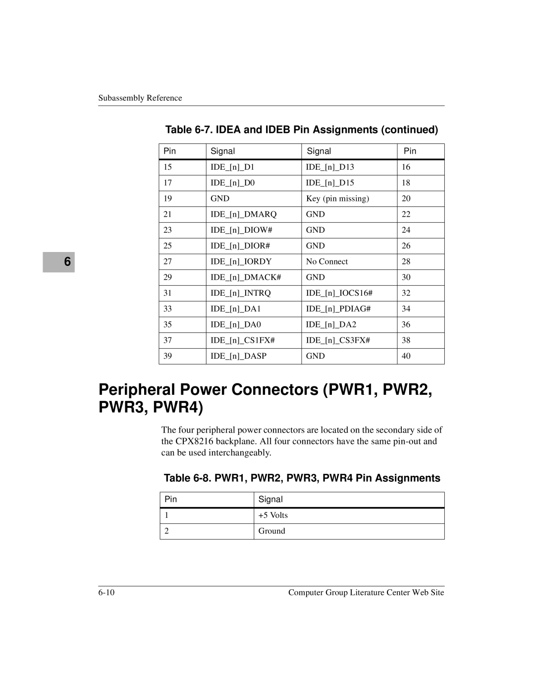
IDE Drive Connectors Idea and Ideb
Idea and Ideb Pin Assignments
Peripheral Power Connectors PWR1, PWR2, PWR3, PWR4
PWR1, PWR2, PWR3, PWR4 Pin Assignments
Primary Front Side I/O Connectors Slots 1-6
Peripheral Signal Connectors SIG1, SIG2, SIG3, SIG4
SIG1, SIG2, SIG3, SIG4 Pin Assignments
12. P3 Connector, I/O Slots 1-6 and 11-16 User I/O
10. P5 Connector, I/O Slots 1-6 User I/O
11. P4 Connector, I/O Slots 1-6 and 11-16 User I/O
Row Z Row a Row B Row C Row D Row E Row F
Row
13. P2 Connector, I/O Slots 1-6 and 11-16 Cpci Bus
Row a Row B Row C Row D Row E
GND VIO BRSVP2B
14. P1 Connector, I/O Slots 1-6 and 11-16 Cpci Bus
AENUM# GND
TRDY# GND
GND SERR# PAR
GND Sdone SBO# PERR# DEVSEL# VIO STOP# LOCK# FRAME# IRDY#
GND REQN# Clkn
TRST#
15. P5 Connector, CPU Slots 7
Primary Front Side CPU Slot Connectors 7
DA1
D14 D15
16. P4 Connector, CPU Slots 7
PDIAG#
D12 D13
CBE2# GND
GND PAR
GND STOP# LOCK# PERR# SERR# FRAME# IRDY# TRDY# Devsel
GND GNT# REQ#
17. P3 Connector, CPU Slots 7
18. P2 Connector, CPU Slot 7 Domain a
GND BRSVP2 FAL# REQ5# GNT5#
GND VIO BRSVP2
GND GA4 GA3 GA2 GA1 GA0 CLK16 RSV CLK15 BRSVP2
19. P2 Connector, CPU Slot 9 Domain B
GND BRSVP2 FAL#
GND CLK12 CLK13 SYSEN#
20. P1 Connector, CPU Slots 7
GND CLK14
GND CLK11
GND Brsvp Hltyn VIO Intp Ints
GND CLK
GND Brsvp RSTN#
GND INTA# INTB# INTC# INTD#
GND TCK TMS TDO TDI
22. P4 Connector, I/O Slots 1-6 and 11-16 User
Secondary Rear Side I/O Connectors
21. P5 Connector, I/O Slots 1-6 and 11-16 User
23. P3 Connector, I/O Slots 1-6 and 11-16 User
24. P5 Connector, CPU Transition Module Slots
CPU Transition Module Connectors Transition Slots 7
GND Rsvd
25. P3 Connector, CPU Transition Slots 7
26. P5 Connector, HSC/Bridge Slots 8
Hot Swap Controller/Bridge Connectors Transition Slots 8
27. P4 Connector, HSC/Bridge Slots 8
KEY Area
28. P3 Connector, HSC Slots 8
29. P2 Connector, HSC Slot
GND BDSEL5# HLTY5# BDSEL7# HLTY15# BDSEL15 BDSEL4# HLTY4#
REQ5# GNT5# GND
30. P2 Connector, HSC Slot
31. P1 Connector, HSC Slots 8
GND Sdone SBO# PERR# Devsel VIO STOP# LOCK# FRAME# IRDY#
GND REQN# Clkn
Bus Connectors-CPX8216T System Only
Pinout Information for See Connector
Primary Front Side I/O Connectors
32. P4 Connector, I/O Slots 1-6
Primary Front Side Slots 1-6
CTFRAMEA# GND
PSF1# Rsvd
VRG VRG RTN
CTFRAMEB# GND
Primary Front Side HSC Connectors
Primary Front Side CPU Connectors
33. P5 Connector, HSC/Bridge Slots 8
Primary Front Side HSC Connectors
34. P4 Connector, HSC Slots 8
Vbat Vbat RTN
GND Hsgntb Inthsc
35. P3 Connector, HSC Slots 8
ON# GND Hsreqb Hsreqa Inthsc
GND Aclk ADOUT# PS1DIN#
36. P2 Connector, HSC Slot
REQ5# GNT5# GND
37. P2 Connector, HSC Slot
38. P1 Connector, HSC Slots 8
Aenum GND
Idsel
39. P5 Connector, I/O Slots 1-6 and 11-16 User
Secondary Rear Side I/O Connectors
Secondary Rear Side CPU Transition Module Connectors
40. P3 Connector, I/O Slots 1-6 and 11-16 User
Alarm Display Panel
Alarm Display Panel Block Diagram
41. Alarm LED Color and Description
Alarm LED Color Description
42. Alarm Display Panel Interface Connector J4
Alarm Display Panel Interface Connector J4
Remote Alarm Connector J1
43. Remote Alarm Connector J1
Power Distribution Panel
AC Power Distribution Panel CPX8216
Dual Input DC Power Distribution Panel CPX8216
Dual Breaker DC Power Distribution Panel CPX8216
DC Power Distribution Panel CPX8216T
Part Number Cable Description
Description Voltage Inputs
44. DC Analog Voltages for H.110 Bus
Selv
Power Supplies
Environmental Characteristics
DC Input
Power Supply Electrical Specifications
AC Input
Output
Table A-1. Total Regulation per Output
Output Power
Adjustment Output Noise
DC Output Voltage
Output Risetime
Overshoot
Holdover Storage
Control Signals
Motorola
Motorola Computer Group Documents
Document Title Publication Number
Table B-1. Related Specifications
Related Specifications
Publication
Document Title and Source Number
ANSI/IEEE
URLs
Index
USB 5-10 connectors CPX8216
IN-3
USB 2-21 video
IN-5