DCT2000 specifications
The Motorola DCT2000 and DCT2500 are digital cable television set-top boxes that have made significant contributions to the evolution of digital television viewing. Designed for cable operators and consumers alike, these models offer a plethora of features that enhance the viewing experience while providing robust solutions for service providers.The Motorola DCT2000 is particularly well-regarded for its reliable performance and user-friendly interface. It supports standard digital cable service, allowing users to access a variety of channels without the need for a separate digital converter. The DCT2000 is equipped with advanced video processing capabilities, which ensure high-quality picture output. With features such as a 480i output for standard definition televisions, this model was designed to bridge the gap between analog and digital content seamlessly.
On the other hand, the Motorola DCT2500 offers more advanced features that cater to the demands of modern viewers. This model not only supports standard definition content but also delivers enhanced capabilities for high-definition video. The DCT2500 is notable for its support of the DOCSIS 2.0 standard, which allows for faster data transmissions. This means that users can enjoy more channels, improved video quality, and a superior overall viewing experience.
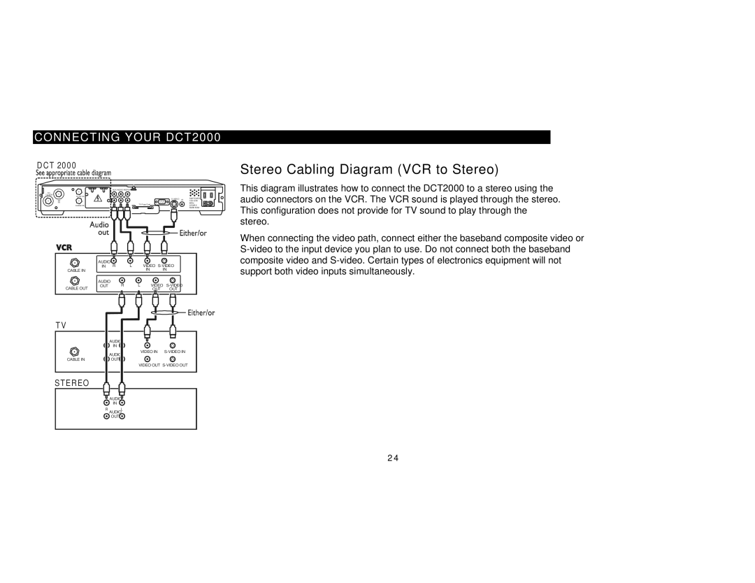
Both the DCT2000 and DCT2500 utilize the Media Cipher technology, ensuring that content remains secure and protected from unauthorized access. This is particularly important for service providers looking to secure their premium channels. Additionally, these set-top boxes feature a range of connectivity options, including standard composite video outputs, S-Video outputs, and coaxial digital audio outputs, making them compatible with a wide range of televisions and audio systems.
Another important aspect of these devices is their interactive capabilities. They support features like on-screen programming guides, which allow users to navigate content easily and even set reminders for their favorite shows. This interactivity enhances the overall user experience and invites viewers to engage more deeply with the content they enjoy.
In summary, both the Motorola DCT2000 and DCT2500 set-top boxes offer a blend of essential features, advanced technologies, and user-friendly characteristics. While the DCT2000 serves as a reliable, standard digital converter, the DCT2500 pushes the envelope with its high-definition capabilities and fast data transmission. Together, these models represent Motorola's commitment to delivering high-quality digital television solutions.

