60x |
Arbiter |
Vcore |
REG |
L2 Cache | SDRAM Expansion |
|
|
| |
256MB |
|
|
| ||
1MB or 2MB |
|
|
| ||
|
|
|
| ||
| SDRAM Expansion | Flash | Serial | Serial | |
MPC7400 | 64 or 256MB | 1MB | 16550 | ||
| |||||
|
|
|
| ||
MPC750 | ECC SDRAM | Flash | Serial |
| |
| |||||
| 64, 128 or 512MB | 16MB | 16550 | ||
|
|
Hawk ASIC |
|
|
|
|
|
|
|
|
|
|
|
|
|
| BUF |
|
|
|
|
|
| ||
| 100 MHz Memory Bus |
|
|
|
| ||||||
|
|
|
| ||||||||
|
|
|
|
|
|
|
|
|
|
|
|
PMC P11 & P12
PCI
PIB
ISA
+3.3V |
REG |
|
|
|
|
|
|
| RTC |
|
|
|
|
|
|
|
|
| NVRAM |
|
|
|
|
| Ethernet | ||||||
|
| FP I/O |
|
| FP I/O |
|
|
| 82559ER |
|
|
|
|
|
|
|
| ||
|
|
|
| ||||||
|
|
|
|
|
|
|
|
|
|
PCI | PMC2 | PMC1 | VME | Ethernet | |
Expansion |
|
| Universe2B | 82559ER | |
|
|
|
46- | Rows | 64- | Rows |
|
|
|
|
|
|
|
|
|
|
|
|
|
|
|
|
|
|
|
| ||||||
pins | D & | pins | A & |
|
|
|
|
|
|
|
|
| ||
| Z |
| C |
|
|
|
|
|
|
|
|
| ||
|
|
|
|
|
|
|
|
|
|
|
|
|
|
|
SCSI |
| Super I/O |
LSI |
| National |
|
|
|
COM1 | COM2 | Parallel |
| ESCC |
|
| CIO | |||
| 85230 |
|
| 8536 | |||
|
|
|
|
|
|
|
|
(712) |
|
|
|
|
|
|
|
Async |
|
|
|
|
|
|
|
|
| P2 MUX |
| ||||
Sync(761) | (Sync) |
|
| PAL |
| ||
|
| MUX |
| ||||
|
|
| (IPMC761) |
| |||
SER3 | SER4 |
|
| P2 |
|
|
|
|
|
|
|
|
|
|
|
P2 |
| P1 |
|
|
|
PMC P14 & P15
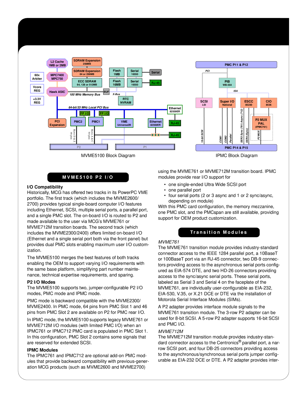
MVME5100 Block Diagram
M V M E 5 1 0 0 P 2 I / O
M V M E 5 1 0 0 P 2 I / O
I/O Compatibility
Historically, MCG has offered two tracks in its PowerPC VME portfolio. The first track (which includes the MVME2600/ 2700) provides typical
The MVME5100 merges the best features of both tracks enabling the OEM to support varying I/O requirements with the same base platform, simplifying part number mainte- nance, technical expertise requirements, and sparing.
P2 I/O Modes
The MVME5100 supports two,
PMC mode is backward compatible with the MVME2300/ MVME2400. In PMC mode, 64 pins from PMC Slot 1 and 46 pins from PMC Slot 2 are available on P2 for PMC rear I/O.
In IPMC mode, the MVME5100 supports legacy MVME761 or MVME712M I/O modules (with limited PMC I/O) when an IPMC761 or IPMC712 PMC card is populated in PMC Slot 1. In this configuration, PMC Slot 2 contains some signals that are reserved for extended SCSI.
IPMC Modules
The IPMC761 and IPMC712 are optional
IPMC Block Diagram
using the MVME761 or MVME712M transition board. IPMC modules provide rear I/O support for
•one
•one parallel port
•four serial ports (2 or 3 async and 1 or 2 sync/async,
depending on module)
With this PMC card configuration, the memory mezzanine, one PMC slot, and the PMCspan are still available, providing support for OEM product customization.
T r a n s i t i o n M o d u l e s
T r a n s i t i o n M o d u l e s
MVME761
The MVME761 transition module provides
A P2 adapter provides interface module signals to the MVME761 transition module. The
MVME712M
The MVME712M transition module provides