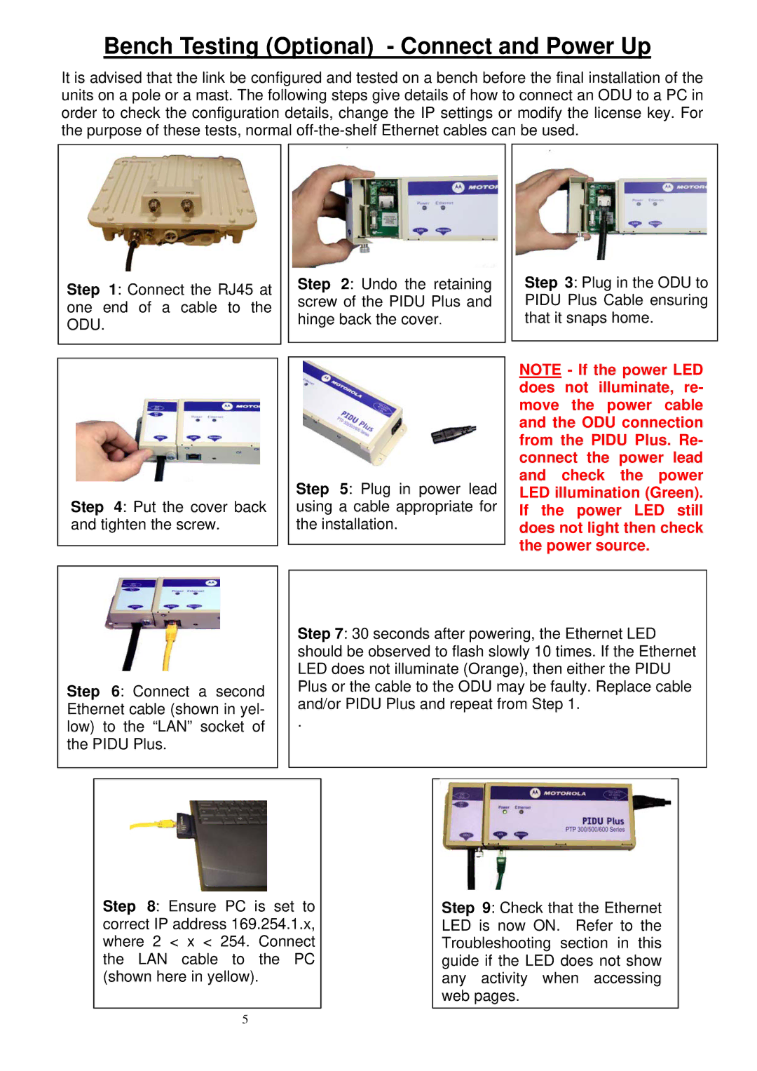
PTP 500, PTP 300 specifications
Motorola's PTP 300 and PTP 500 series are engineered to provide robust point-to-point microwave solutions tailored for various applications, including backhaul for broadband networks, enterprise connectivity, and more. These systems are designed to deliver reliable, high-capacity wireless connectivity, making them integral components of modern communication infrastructures.The PTP 300 series operates in the 2.5 GHz frequency band, allowing for long-range communication capabilities of up to 100 miles, depending on environmental conditions and deployment scenarios. This series supports data rates of up to 56 Mbps, making it suitable for applications that demand high-speed data transmission. It utilizes advanced MIMO technology, which enhances throughput and wireless reliability by utilizing multiple antennas to transmit and receive data simultaneously.
The PTP 500 series, on the other hand, operates in both the 5 GHz and the 4.9 GHz frequency bands. This versatility allows operators to select the optimal frequency for their specific environment, helping to mitigate interference and optimize performance. The PTP 500 series can achieve even higher data rates, reaching up to 300 Mbps, and can cover distances exceeding 30 miles.
Both series feature robust security mechanisms, including AES encryption, to safeguard data integrity and confidentiality. Their inherent design incorporates efficient power consumption and minimal latency, making them suitable for real-time applications like VoIP and video conferencing.
Installation and maintenance of the PTP 300 and PTP 500 systems are user-friendly, owing to a web-based management interface, which simplifies configuration and troubleshooting. They also include auto-alignment features that facilitate quick deployment and ensure optimal signal strength.
In terms of physical characteristics, both the PTP 300 and PTP 500 models are built to withstand harsh environmental conditions, sporting durable enclosures that adhere to IP-rated standards. This resilience makes them apt for outdoor installations.
Overall, the Motorola PTP 300 and PTP 500 series deliver dependable, high-throughput microwave technology, with features that cater to various communication needs while ensuring scalability, security, and ease of use. As networks evolve to accommodate higher bandwidth demands, these systems represent a strong choice for enterprises and service providers alike.

