5. Software Installation Information
To install NPort Administration Suite, insert the NPort Document & Software CD into your computer’s
RJ45
RJ45 Port RJ45 Connector | DB25 Female DB25 | ||
|
|
| Male |
|
|
| |
8. Specifications
Power requirements |
|
NPort | 12 to 48 VDC, 305 mA at 12V (max.) |
Installation CD window opens, click on the Installation button, and then follow the instructions on the screen. To view detailed information about NPort 5200 Administration Suite, click on the Documents button, and then select “NPort 5200 Series User’s Guide” to open the pdf version of this user’s guide. The PComm Lite program is also included in the Documentation & Software CD free of charge. Install PComm Lite to use the Serial Console for configuring the IP address for the first time.
6. Pin Assignments and Cable |
NPort
8 pins
DSR 1 ![]()
RTS 2
GND 3
TxD 4
RxD 5
DCD 6
CTS 7
DTR 8
|
|
|
| |
|
|
|
| |
|
|
|
| Device |
|
|
|
|
|
Cable Wiring | 25 pins | |||
20 | DTR | |||
5 | CTS | |||
7 | GND | |||
3 | RxD | |||
2 | TxD | |||
8 | DCD | |||
4 | RTS | |||
6 | DSR | |||
NPort | 12 to 48 | VDC, 305 mA at 12V (max.) |
NPort | 12 to 48 | VDC, 359.6 mA at 12V (max.) |
NPort | 12 to 48 | VDC, 509.4 mA at 12 V (max.) |
Operating temp. |
|
|
0 to 55◦C (32 to 131◦F) | for standard models | |
for | ||
|
Terminal Block Wiring
RJ45
RJ45 Port RJ45 Connector | DB25 Male DB25 | ||
|
|
| Female |
|
|
| |
Operating humidity |
5 to 95% RH |
Dimensions (W×D×H) |
Serial Device
Signals
RxD
TxD
CTS
RTS
GND
Rx+
Rx-
Tx+ / Data+
NPort | ||
Tx |
| |
Rx | P1 | |
RTS | RS- | |
CTS | 232 | |
GND |
| |
T+ | P2 | |
T- | ||
RS- | ||
R+/D+ | ||
NPort
8 pins
DSR 1 ![]()
RTS 2
GND 3
TxD 4
RxD 5
DCD 6
CTS 7
DTR 8
|
|
|
| |
|
|
|
| |
|
|
|
| Device |
|
|
|
|
|
Cable Wiring | 25 pins | |||
6 | DTR | |||
4 | CTS | |||
7 | GND | |||
2 | RxD | |||
3 | TxD | |||
8 | DCD | |||
5 | RTS | |||
20 | DSR | |||
NPort 5210/5230/5232/ | 90 × 100.4 × 22 mm | |
3.54 | × 3.95 × 0.87 in | |
NPort 5210/5230/5232/ | 67 × 100.4 × 22 mm | |
2.64 | × 3.95 × 0.87 in | |
NPort | 90 × 100.4 × 35 mm | |
(including ears) | 3.54 | × 3.95 ×1.37 in |
NPort | 67 × 100.4 × 35 mm | |
GND
485/422 | |||
GND | |||
|
| ||
RJ45
RJ45 Port RJ45 Connector | DB9 Female DB9 Male |
(without ears) | 2.64 × 3.95 × 1.37 in |
Surge protection
NPort |
15 KV ESD for serial port
Note:
NPort
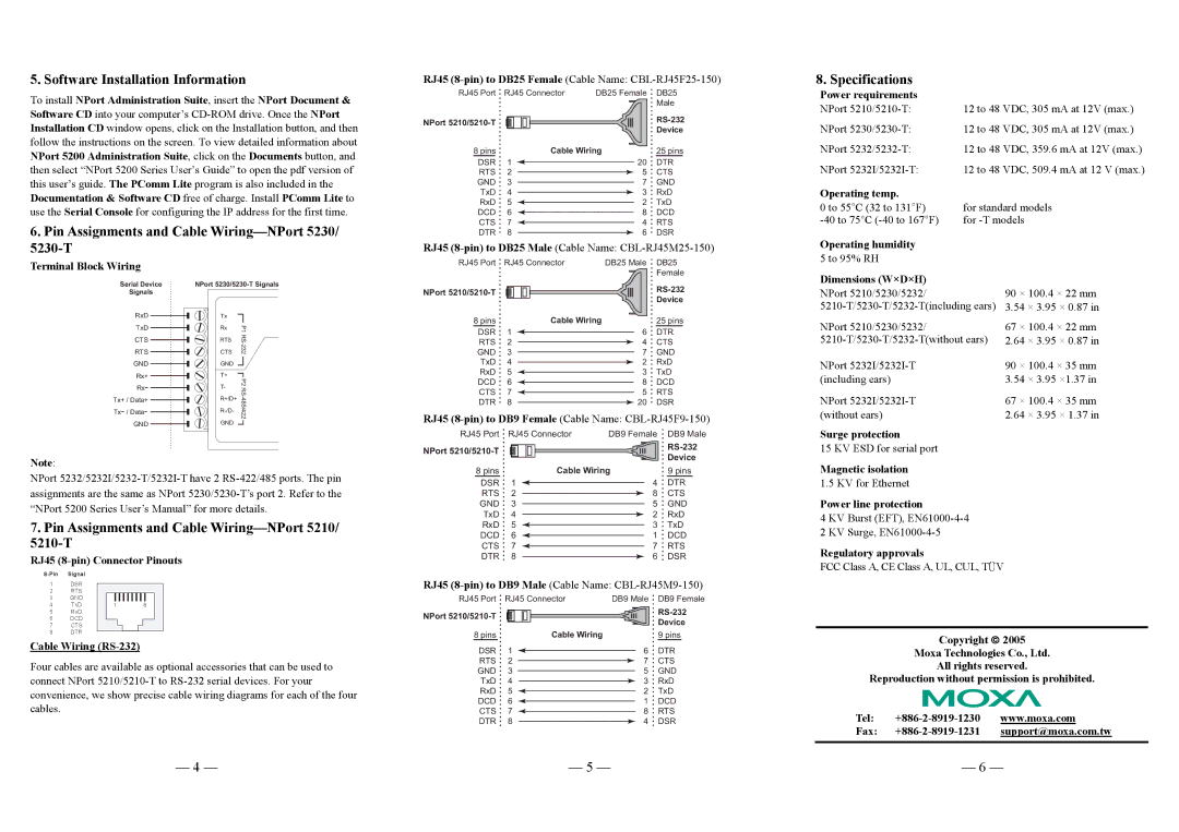
7.Pin Assignments and Cable Wiring—NPort 5210/ 5210-T
RJ45 (8-pin) Connector Pinouts
8 pins |
|
|
| Cable Wiring | |
DSR | 1 |
|
|
|
|
|
| ||||
RTS | 2 |
|
|
|
|
|
|
|
| ||
GND | 3 |
|
|
|
|
|
|
|
| ||
TxD | 4 |
|
|
|
|
|
|
|
| ||
RxD | 5 |
|
|
|
|
|
|
|
| ||
DCD | 6 |
|
|
|
|
|
|
|
| ||
CTS | 7 |
|
|
|
|
|
|
|
| ||
DTR | 8 |
|
|
|
|
|
|
| |||
Device
9pins
4 DTR
8 CTS
5 GND
2 RxD
3 TxD
1 DCD
7 RTS
6 DSR
Magnetic isolation
1.5 KV for Ethernet
Power line protection
4KV Burst (EFT),
2KV Surge,
Regulatory approvals
FCC Class A, CE Class A, UL, CUL, TÜV
1DSR
2RTS
3 | GND |
|
|
4 | TxD | 1 | 8 |
RJ45
RJ45 Port RJ45 Connector | DB9 Male DB9 Female |
5RxD
6DCD
7CTS
8DTR
Cable Wiring (RS-232)
Four cables are available as optional accessories that can be used to connect NPort
NPort
8 pins | Cable Wiring |
DSR 1 ![]()
RTS 2
GND 3
TxD 4
RxD 5 ![]()
DCD 6 ![]()
CTS 7 ![]()
DTR 8
Device
9 pins
6DTR
7CTS
5GND
3RxD
2TxD
1DCD
8RTS
4DSR
Copyright ♥ 2005
Moxa Technologies Co., Ltd.
All rights reserved.
Reproduction without permission is prohibited.
Tel:
Fax:
— 4 — | — 5 — | — 6 — |