NPort 5200 Series
Quick Installation Guide
Fifth Edition, November 2005
1. Overview
The NPort 5200 Series of compact
Note:
2. Package Checklist
Before installing NPort 5200, verify that the package contains the following items:
y1 NPort 5200
yDocumentation & Software CD
yNPort 5200 Series Quick Installation Guide
Optional Accessories |
| |
y | ||
y | RJ45 | |
y | RJ45 | |
y
y
y
Notify your sales representative if any of the above items is missing or damaged.
3. Hardware Introduction
The NPort 5200 series of device servers are used to control
NPort | NPort | ||||
RJ45 10/100M |
|
| Reset | Terminal Block | |
Ethernet port |
|
| button | Power input | |
V- V+RESET | 10/100M | V- V+ |
| RESET 10/100M | |
Ethernet |
| Ethernet | |||
Ready |
| screw hole | Ready |
|
|
Link |
|
| Link |
|
|
P1 |
|
| P1 |
|
|
P2 |
|
| P2 |
|
|
| 5210 |
|
|
| 523010 |
Industrial |
|
| Industrial | ||
|
| Wallmount | P1 | P2 | |
P1 | P2 | screw hole | Tx Rx RTS | CTS | GND T+ T- R+/D+ |
| |||||
serial ports |
| Terminal Block | |||
NPort | NPort | ||||
RJ45 10/100M |
|
| Reset |
|
| Terminal Block | |||
Ethernet port |
|
| button |
|
| Power input | |||
V- | V+ | RESET | 10/100M |
| V- | V+ |
| RESET 10/100M | |
| Ethernet |
| Ethernet | ||||||
Ready |
|
|
| screw hole | Ready |
|
|
| |
Link |
|
|
|
| Link |
|
|
| |
P1 |
|
|
|
| P1 |
|
|
|
|
P2 |
|
|
|
| P2 |
|
|
|
|
|
|
| 523210 |
|
|
|
|
| 5232I10 |
| Industrial |
|
|
|
| Industrial | |||
P1 | P2 | Wallmount |
| P1 | P2 | ||||
Tx Rx | RTS CTS | GND T+ T- R+/D+ | screw hole | Tx | Rx | RTS | CTS | GND T+ T- R+/D+ | |
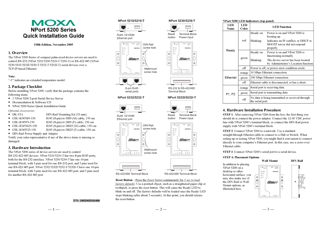
NPort 5200 LED Indicators (top panel)
LED | LED |
| LED Function |
Name | Color |
| |
|
| ||
|
| Steady on: | Power is on and NPort 5200 is |
| red |
| booting up. |
| Blinking: | Indicates an IP conflict, or DHCP or | |
|
|
| BOOTP server did not respond |
Ready |
|
| properly. |
| Steady on: | Power is on and NPort 5200 is | |
|
| ||
| green |
| functioning normally. |
| Blinking: | The device server has been located | |
|
|
| by Administrator’s Location function |
| off | Power is off, or power error condition exists. | |
| orange | 10 Mbps Ethernet connection. | |
|
|
| |
Ethernet | green | 100 Mbps Ethernet connection. | |
| off | Ethernet cable is disconnected, or has a short. | |
|
|
| |
| orange | Serial port is receiving data. | |
|
|
| |
P1, P2 | green | Serial port is transmitting data. | |
|
|
| |
| off | No data is being transmitted or received through | |
| the serial port. | ||
|
| ||
4. Hardware Installation Procedure
STEP 1: After removing NPort 5200 from the box, the first thing you should do is connect the power adaptor. Connect the
STEP 2: Connect NPort 5200 to a network. Use a standard
STEP 3: Connect NPort 5200’s serial port to a serial device.
both for the
Reset
STEP 4: Placement Options
In addition to placing NPort 5200 on a desktop or other horizontal surface, you may also make use of the
Wall Mount | ||
V- V+ | RESET 10/100M |
|
Ethernet |
| |
Ready |
|
|
Link |
|
|
P1 |
|
|
P2 |
|
|
| 52105210 |
|
| Industrial |
|
P/N: 1802002010400
the reset button.
P1 | P2 |
— 1 — | — 2 — | — 3 — |