Hardware Setup
Power Supply
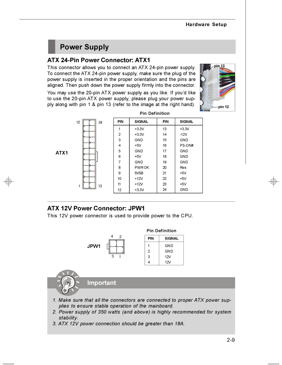
ATX 24-Pin Power Connector: ATX1
This connector allows you to connect an ATX
You may use the
Pin Definition
pin 13
![]() pin 12
pin 12
12 | 24 |
ATX1 |
|
1 | 13 |
PIN | SIGNAL | PIN | SIGNAL |
1 | +3.3V | 13 | +3.3V |
2 | +3.3V | 14 | |
3 | GND | 15 | GND |
4 | +5V | 16 | |
5 | GND | 17 | GND |
6 | +5V | 18 | GND |
7 | GND | 19 | GND |
8 | PWROK | 20 | Res |
9 | 5VSB | 21 | +5V |
10 | +12V | 22 | +5V |
11 | +12V | 23 | +5V |
12 | +3.3V | 24 | GND |
ATX 12V Power Connector: JPW1
This 12V power connector is used to provide power to the CPU.
JPW1
4 | 2 |
3 | 1 |
Pin Definition
PIN | SIGNAL |
|
|
1 | GND |
2 | GND |
3 | 12V |
4 | 12V |
Important
1.Make sure that all the connectors are connected to proper ATX power sup- plies to ensure stable operation of the mainboard.
2.Power supply of 350 watts (and above) is highly recommended for system stability.
3.ATX 12V power connection should be greater than 18A.