SECTION 3: SET-UP
NOTE: This operator’s manual covers various models of mowers. Follow instructions pertaining to your unit only.
It is suggested that this manual be read in its entirety before attempting to assemble or operate. Keep this manual in a safe place for future reference and for ordering replacement parts.
This unit is shipped WITHOUT GASOLINE or OIL. After assembly, service engine with gasoline and oil as instructed in the separate engine manual packed with your unit.
NOTE: Reference to right, left, front or back of the lawn mower is from the operating position only, unless otherwise stated.
Tools Required for Assembly
(2) | 1/2" Wrenches | (1) | 9/16" Wrench |
(1) | 7/16" Wrench | (1) | 3/4" Wrench |
NOTE: Locknuts cannot be threaded onto a bolt by hand, a wrench is required for assembly. This type of nut is used where vibrations occur.
Remove the lawn mower and all parts from the carton. Make certain all parts and literature have been removed from the carton before the carton is discarded.
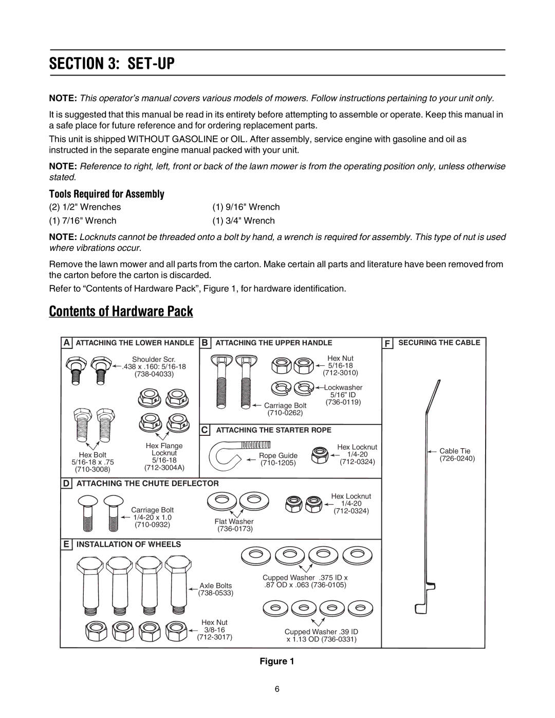
Refer to “Contents of Hardware Pack”, Figure 1, for hardware identification.
Contents of Hardware Pack
A ATTACHING THE LOWER HANDLE B ATTACHING THE UPPER HANDLE | F SECURING THE CABLE |
| Shoulder Scr. |
| Hex Nut |
| .438 x .160: |
| |
|
| ||
|
|
| Lockwasher |
|
|
| 5/16” ID |
|
| Carriage Bolt | |
|
|
| |
|
|
| |
|
| C ATTACHING THE STARTER ROPE | |
| Hex Flange |
| Hex Locknut |
Hex Bolt | Locknut | Rope Guide | |
|
| ||
DATTACHING THE CHUTE DEFLECTOR
| Hex Locknut |
Carriage Bolt | |
Flat Washer | ||
|
EINSTALLATION OF WHEELS
![]() Cable Tie
Cable Tie
Axle Bolts
Hex Nut
Cupped Washer .375 ID x
.87 OD x .063
Cupped Washer .39 ID x 1.13 OD
Figure 1
6