Final Adjustments

Auger Control Adjustment

Check the adjustment of the auger control as follows:

Push forward on the auger control until the small rubber bumper contacts the upper handle. There should be slack in the cable. See Figure 5 .

Release the auger control. The cable should be

straight. Make certain you can depress the auger control against the left handle completely without using excess force.

If adjustment is necessary, proceed as follows:

Loosen the jam nut and thread the cable in (for less slack) or out (for more slack) as necessary. See Figure 5 .

Recheck the adjustment before retightening the jam nut against the cable.

Auger

Control

Z-End

Jam Nut

Auger

Control Cable

Figure 5

Skid Shoe Adjustment

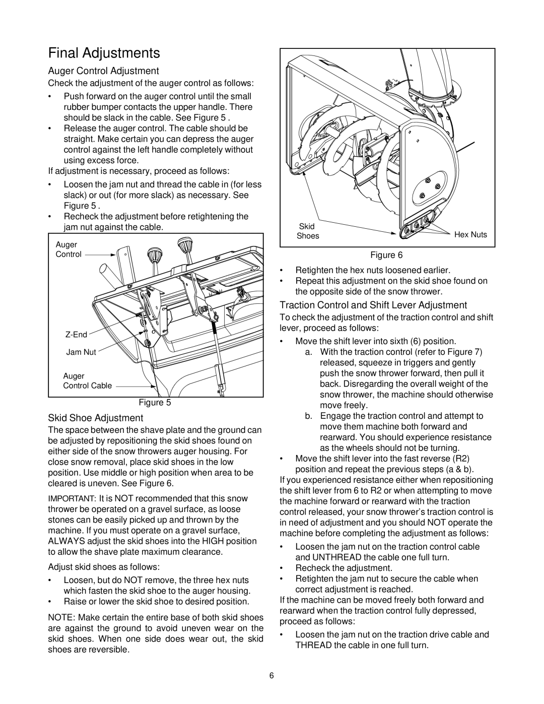
The space between the shave plate and the ground can be adjusted by repositioning the skid shoes found on either side of the snow throwers auger housing. For close snow removal, place skid shoes in the low position. Use middle or high position when area to be cleared is uneven. See Figure 6.

IMPORTANT: It is NOT recommended that this snow thrower be operated on a gravel surface, as loose stones can be easily picked up and thrown by the machine. If you must operate on a gravel surface, ALWAYS adjust the skid shoes into the HIGH position to allow the shave plate maximum clearance.

Adjust skid shoes as follows:

Loosen, but do NOT remove, the three hex nuts which fasten the skid shoe to the auger housing.

Raise or lower the skid shoe to desired position.

NOTE: Make certain the entire base of both skid shoes are against the ground to avoid uneven wear on the skid shoes. When one side does wear out, the skid shoes are reversible.

Skid

Hex Nuts

Shoes

Figure 6

Retighten the hex nuts loosened earlier.

Repeat this adjustment on the skid shoe found on the opposite side of the snow thrower.

Traction Control and Shift Lever Adjustment

To check the adjustment of the traction control and shift lever, proceed as follows:

Move the shift lever into sixth (6) position.

a.With the traction control (refer to Figure 7) released, squeeze in triggers and gently push the snow thrower forward, then pull it back. Disregarding the overall weight of the snow thrower, the machine should otherwise move freely.

b.Engage the traction control and attempt to move them machine both forward and rearward. You should experience resistance as the wheels should not be turning.

Move the shift lever into the fast reverse (R2) position and repeat the previous steps (a & b).

If you experienced resistance either when repositioning the shift lever from 6 to R2 or when attempting to move the machine forward or rearward with the traction control released, your snow thrower’s traction control is in need of adjustment and you should NOT operate the machine before completing the adjustment as follows:

Loosen the jam nut on the traction control cable and UNTHREAD the cable one full turn.

Recheck the adjustment.

Retighten the jam nut to secure the cable when

correct adjustment is reached.

If the machine can be moved freely both forward and rearward when the traction control fully depressed, proceed as follows:

Loosen the jam nut on the traction drive cable and THREAD the cable in one full turn.

6

Page 6
Image 6
MTD 31AH5Q3G401, 31AH5C3F401 manual Final Adjustments, Auger Control Adjustment, Skid Shoe Adjustment

31AH5C3F401, 31AH5Q3G401 specifications

The MTD 31AH5Q3G401 and MTD 31AH5C3F401 are advanced power MOSFETs designed for various high-efficiency applications. These components are notable for their superior performance in energy conversion and management, making them ideal for use in automotive, industrial, and consumer electronics sectors.

One of the main features of the MTD 31AH5Q3G401 is its low on-resistance (Rds(on)), which significantly contributes to enhanced energy efficiency. Low Rds(on) translates to lower conduction losses during operation, leading to reduced heat generation. This characteristic is crucial in applications where thermal management is a concern, allowing designers to minimize the size of heat sinks and cooling systems.

The MTD 31AH5C3F401 complements this with a fast switching speed, which is essential for high-frequency applications such as switch-mode power supplies (SMPS) and DC-DC converters. The rapid transition from on to off state results in decreased switching losses, allowing for higher overall efficiency in power conversion processes.

Both models utilize a robust silicon technology that enhances their reliability and durability under various operational conditions. Their maximum voltage ratings can easily accommodate voltage transients encountered in automotive applications, ensuring they can handle high-stress environments without compromising performance.

In terms of packaging, the MTD 31AH5Q3G401 and 31AH5C3F401 are available in compact forms, enabling designers to save space on PCBs while maintaining a high power density. The integration of thermal management features within the package reduces thermal resistance, further aiding in effective heat dissipation, which is critical in prolonged use.

A common characteristic of both devices is their ability to operate in a wide range of temperatures, which makes them suitable for both outdoor and indoor applications. They are capable of delivering reliable performance across different environmental conditions, enhancing their usability in various sectors.

In summary, the MTD 31AH5Q3G401 and 31AH5C3F401 are exemplary components featuring low on-resistance, fast switching capabilities, robust silicon technology, and compact packaging. These attributes position them as ideal choices for designers looking to enhance the efficiency and reliability of their electronic systems while managing thermal challenges effectively. With their versatility and strong performance metrics, these MOSFETs are set to play a vital role in the future of power electronics.