TIRE PRESSURE (Pneumatic Tires) | CHUTE CRANK |
The tires are overinflated for shipping purposes. Check tire pressure and reduce to 15 to 20 psi. Refer to tire sidewalls for recommended tire pressure.
NOTE: If the tire pressure is not equal in both tires, the unit may pull to one side or the other.
SECTION 6: CONTROLS
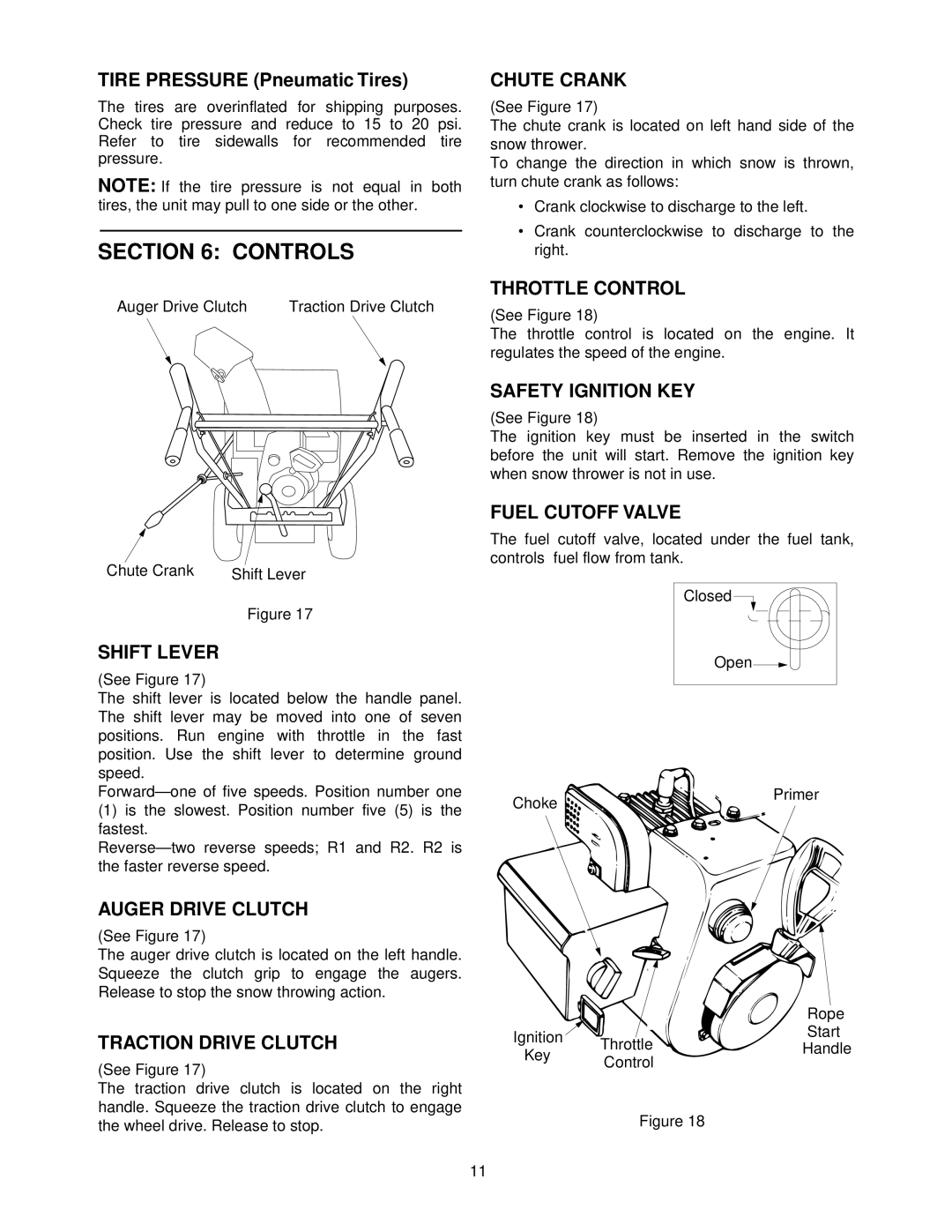
Auger Drive Clutch | Traction Drive Clutch |
Chute Crank | Shift Lever |
Figure 17
SHIFT LEVER
(See Figure 17)
The shift lever is located below the handle panel. The shift lever may be moved into one of seven positions. Run engine with throttle in the fast position. Use the shift lever to determine ground speed.
(1)is the slowest. Position number five (5) is the fastest.
AUGER DRIVE CLUTCH
(See Figure 17)
The auger drive clutch is located on the left handle. Squeeze the clutch grip to engage the augers. Release to stop the snow throwing action.
TRACTION DRIVE CLUTCH
(See Figure 17)
The traction drive clutch is located on the right handle. Squeeze the traction drive clutch to engage the wheel drive. Release to stop.
(See Figure 17)
The chute crank is located on left hand side of the snow thrower.
To change the direction in which snow is thrown, turn chute crank as follows:
•Crank clockwise to discharge to the left.
•Crank counterclockwise to discharge to the right.
THROTTLE CONTROL
(See Figure 18)
The throttle control is located on the engine. It regulates the speed of the engine.
SAFETY IGNITION KEY
(See Figure 18)
The ignition key must be inserted in the switch before the unit will start. Remove the ignition key when snow thrower is not in use.
FUEL CUTOFF VALVE
The fuel cutoff valve, located under the fuel tank, controls fuel flow from tank.
Closed ![]()
Open![]()
Choke | Primer |
|
|
| Rope | |
Ignition | Throttle | Start | |
Handle | |||
Key | |||
Control |
| ||
|
| ||
| Figure 18 |
|
11