769-03096A specifications
The MTD 769-03096A is a powerful and versatile lawn mower attachment designed to enhance lawn care efficiency. This innovative product is primarily utilized with various MTD lawn mower models, bringing advanced technology and user-friendly features to the forefront of gardening equipment.One of the standout features of the MTD 769-03096A is its durable construction, which ensures long-lasting performance even in tough mowing conditions. Made from high-quality materials, this attachment is engineered to withstand the wear and tear often associated with outdoor use. Its robust build makes it capable of tackling thick grass and overgrown areas, making it an ideal choice for homeowners and landscaping professionals alike.
The technology behind the MTD 769-03096A includes a powerful cutting mechanism that promotes efficient grass cutting. Its precision-engineered blades are designed to provide a clean and even cut, which is essential for maintaining a healthy lawn. With a cutting width that allows for broad coverage, users can complete their mowing tasks in less time, ultimately increasing productivity.
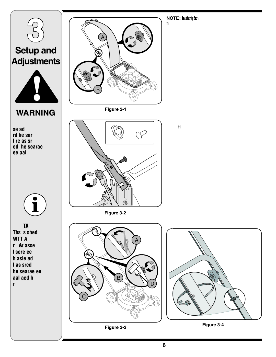
In addition to its cutting capability, the MTD 769-03096A emphasizes ease of use. Its quick-connect mount system allows for easy attachment and detachment from compatible lawn mowers, saving valuable time during maintenance tasks. Additionally, the design incorporates an adjustable cutting height feature, enabling users to tailor their mowing height according to specific lawn needs. This adaptability is essential for promoting optimal grass health and appearance.
Another notable characteristic is the attachment's lightweight design, which contributes to ease of maneuverability. Even in challenging terrain, users can navigate their lawn with minimal effort, reducing fatigue during extended mowing sessions.
Furthermore, the MTD 769-03096A is compatible with a wide range of MTD mower models, adding to its versatility. This compatibility ensures that users who already own MTD equipment can easily integrate this attachment into their existing setup.
In conclusion, the MTD 769-03096A lawn mower attachment stands out for its durable construction, advanced cutting technology, user-friendly features, and versatility. Whether for residential or professional use, this attachment represents a valuable tool for effective lawn maintenance, catering to the needs of a wide range of users. Its ability to provide a clean cut, adjust cutting heights, and connect easily with various mowers makes it a noteworthy addition to the MTD product line.

