6

Adjustments

&

Maintenance

WARNING

Disconnect the spark plug wire and ground it against the engine to prevent unintended starting.

NEVER attempt to make any adjustments while the engine is running, except where specified in the operator’s manual.

Before servicing, repairing, or inspecting, disengage the control bail and stop engine. Wait until all moving parts have come to a complete stop.

WARNING: NEVER attempt to make any adjustments while the engine is running, except where specified in the operator’s manual.

��������

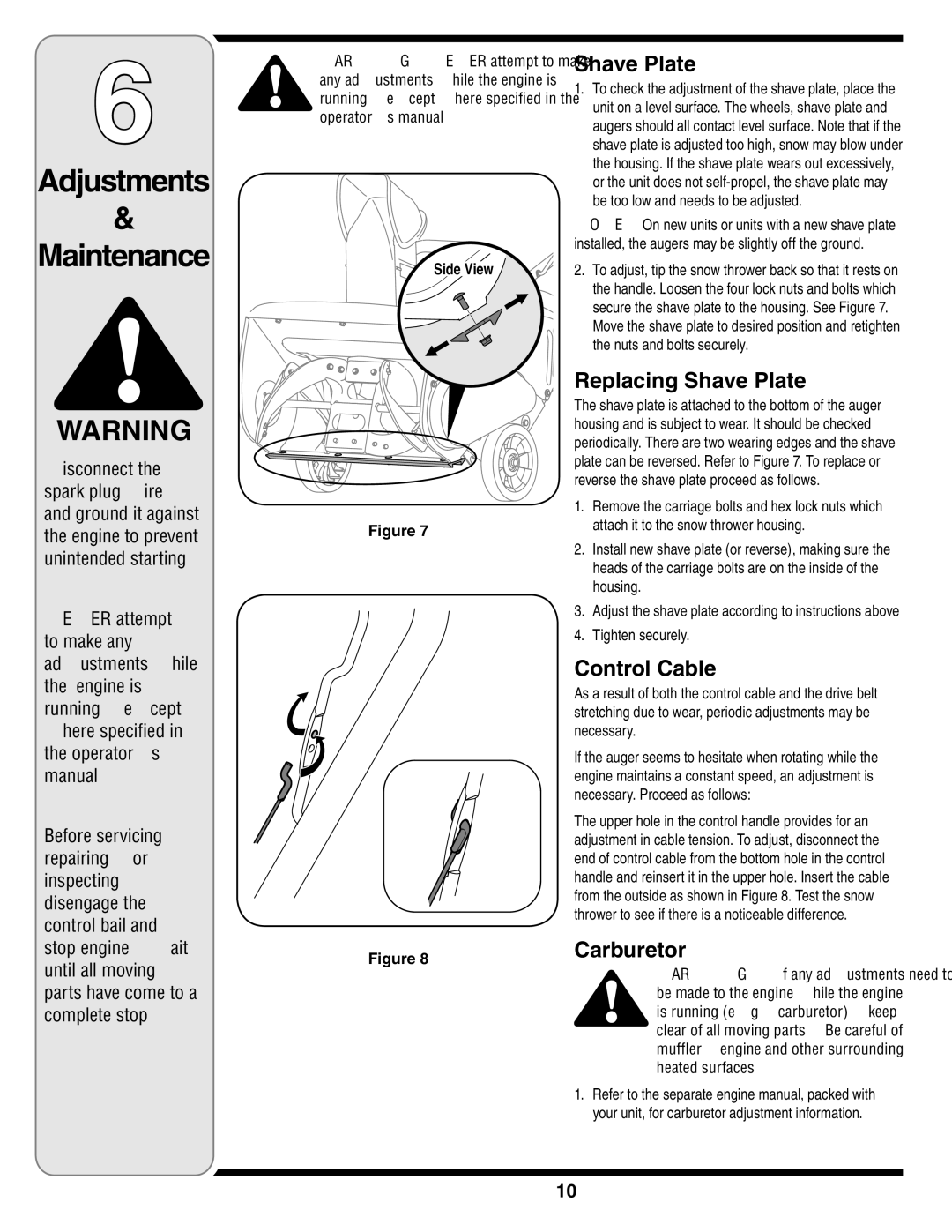
Figure 7

Figure 8

Shave Plate

1.To check the adjustment of the shave plate, place the unit on a level surface. The wheels, shave plate and augers should all contact level surface. Note that if the shave plate is adjusted too high, snow may blow under the housing. If the shave plate wears out excessively, or the unit does not self-propel, the shave plate may be too low and needs to be adjusted.

NOTE: On new units or units with a new shave plate installed, the augers may be slightly off the ground.

2.To adjust, tip the snow thrower back so that it rests on the handle. Loosen the four lock nuts and bolts which secure the shave plate to the housing. See Figure 7.

Move the shave plate to desired position and retighten the nuts and bolts securely.

Replacing Shave Plate

The shave plate is attached to the bottom of the auger housing and is subject to wear. It should be checked periodically. There are two wearing edges and the shave plate can be reversed. Refer to Figure 7. To replace or reverse the shave plate proceed as follows.

1.Remove the carriage bolts and hex lock nuts which attach it to the snow thrower housing.

2.Install new shave plate (or reverse), making sure the heads of the carriage bolts are on the inside of the housing.

3.Adjust the shave plate according to instructions above

4.Tighten securely.

Control Cable

As a result of both the control cable and the drive belt stretching due to wear, periodic adjustments may be necessary.

If the auger seems to hesitate when rotating while the engine maintains a constant speed, an adjustment is necessary. Proceed as follows:

The upper hole in the control handle provides for an adjustment in cable tension. To adjust, disconnect the end of control cable from the bottom hole in the control handle and reinsert it in the upper hole. Insert the cable from the outside as shown in Figure 8. Test the snow thrower to see if there is a noticeable difference.

Carburetor

WARNING: If any adjustments need to be made to the engine while the engine is running (e.g. carburetor), keep clear of all moving parts. Be careful of muffler, engine and other surrounding heated surfaces.

1.Refer to the separate engine manual, packed with your unit, for carburetor adjustment information.

10

Page 10
Image 10
MTD 2B5&295, E2B5 & E295, E2B5&E295, 2B5 & 295 Adjustments Maintenance, Replacing Shave Plate, Control Cable, Carburetor

2B5 & 295, 2B5&295, E2B5&E295, E2B5 & E295 specifications

MTD 2B5 and E295 are part of a series of advanced technologies used in various industrial applications, offering enhanced performance and versatility. MTD stands for "Manufacturing Technology Development," which emphasizes the importance of innovative approaches in today’s fast-paced manufacturing environment.

One of the standout features of the MTD 2B5 series is its ability to efficiently integrate with existing industrial processes. It provides seamless compatibility with numerous systems, allowing for straightforward implementation without extensive modifications. This characteristic is crucial for businesses aiming to upgrade their technology without incurring significant downtime or costs.

The E295 model is characterized by its robust design and durability, making it suitable for demanding operational conditions. It brings forth advanced material science, which includes improvements in wear resistance and thermal stability. This ensures that the E295 can withstand extreme temperatures and abrasive environments while maintaining operational efficiency.

Both models employ cutting-edge automation technologies, which streamline operations and reduce human error. This automation not only improves productivity but also enhances safety in the workplace. With features like predictive maintenance, these technologies allow operators to monitor performance in real-time, significantly reducing the risk of unexpected failures.

Another notable aspect of the MTD 2B5 and E295 is their energy efficiency. The integration of smart algorithms optimizes power usage, helping companies to reduce their carbon footprint and operational costs. This sustainability aspect is becoming increasingly important in today’s industrial landscape, where companies are under pressure to adopt greener practices.

Moreover, the modular design of both MTD 2B5 and E295 facilitates quick scalability. This feature allows businesses to tailor their setups according to fluctuating demands without overcommitting resources. It ensures that companies can scale up or down quickly in response to market changes.

In conclusion, MTD 2B5 and E295 offer a compelling mix of advanced features, innovative technology, and adaptability, making them ideal choices for modern industries looking to enhance their manufacturing processes. Their combination of durability, efficiency, and smart automation aligns perfectly with the current trends in the industrial sector, where the focus is on innovation and sustainability. As businesses continue to evolve, these technologies will play a significant role in shaping the future of manufacturing, ensuring that they remain competitive and efficient.