To Stop Engine

1.To stop engine, turn ignition key counter-clockwise. Disconnect the spark plug wire from the spark plug to prevent accidental starting while equipment is unattended.

To help prevent possible freeze-up of starter, proceed as follows:

1.Run engine for a few minutes before stopping to help dry off any moisture on the engine.

2.Electric Starter (optional): Connect power cord to switch box on engine, then to 120 volt AC receptacle. With the engine running, push starter button and spin the starter for several seconds. The unusual sound made by spinning the starter will not harm engine or starter. Disconnect the power cord from receptacle first, and then from switch box.

3.Recoil Starter: With engine running, pull starter rope with a rapid, continuous full arm stroke three or four times. Pulling the starter rope will produce a loud clatter- ing sound, which is not harmful to the engine or starter.

4.Wipe all snow and moisture from the carburetor cover in the area of the control levers. Also, move control levers back and forth several times. Leave choke control in the FULL choke position.

5.Remove ignition key and disconnect spark plug wire to prevent accidental starting.

Operating Tips

1.Discharge snow downwind whenever possible. Slightly overlap each previously cleared path.

2.Lifting up on the handle will allow the rubber on the augers to propel the snow thrower forward. Pushing downward on the handle will raise the augers off the ground and stop forward motion.

NOTE: Excessive upward pressure on the handle will result in premature wear on the rubber auger blades which would not be covered by warranty.

3.Run the engine for a few minutes before stopping to help dry any moisture on the engine.

4.Clean the snow thrower thoroughly after each use.

5

Operation

WARNING

Muffler, engine and surrounding areas become hot and can cause a burn. Do not touch.

Operating the Snow Thrower

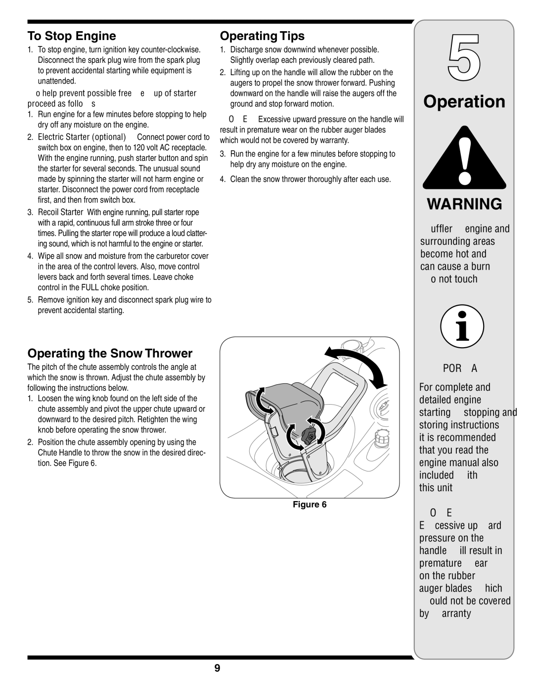
The pitch of the chute assembly controls the angle at which the snow is thrown. Adjust the chute assembly by following the instructions below.

1. Loosen the wing knob found on the left side of the chute assembly and pivot the upper chute upward or downward to the desired pitch. Retighten the wing knob before operating the snow thrower.

2. Position the chute assembly opening by using the Chute Handle to throw the snow in the desired direc- tion. See Figure 6.

Figure 6

IMPORTANT:

For complete and detailed engine starting, stopping and storing instructions, it is recommended that you read the engine manual also included with

this unit.

NOTE:

Excessive upward pressure on the handle will result in premature wear on the rubber auger blades which would not be covered by warranty.

9

Page 9
Image 9
MTD E2B5&E295, E2B5 & E295, 2B5&295, 2B5 & 295 warranty To Stop Engine, Operating Tips, Operating the Snow Thrower, This unit

2B5 & 295, 2B5&295, E2B5&E295, E2B5 & E295 specifications

MTD 2B5 and E295 are part of a series of advanced technologies used in various industrial applications, offering enhanced performance and versatility. MTD stands for "Manufacturing Technology Development," which emphasizes the importance of innovative approaches in today’s fast-paced manufacturing environment.

One of the standout features of the MTD 2B5 series is its ability to efficiently integrate with existing industrial processes. It provides seamless compatibility with numerous systems, allowing for straightforward implementation without extensive modifications. This characteristic is crucial for businesses aiming to upgrade their technology without incurring significant downtime or costs.

The E295 model is characterized by its robust design and durability, making it suitable for demanding operational conditions. It brings forth advanced material science, which includes improvements in wear resistance and thermal stability. This ensures that the E295 can withstand extreme temperatures and abrasive environments while maintaining operational efficiency.

Both models employ cutting-edge automation technologies, which streamline operations and reduce human error. This automation not only improves productivity but also enhances safety in the workplace. With features like predictive maintenance, these technologies allow operators to monitor performance in real-time, significantly reducing the risk of unexpected failures.

Another notable aspect of the MTD 2B5 and E295 is their energy efficiency. The integration of smart algorithms optimizes power usage, helping companies to reduce their carbon footprint and operational costs. This sustainability aspect is becoming increasingly important in today’s industrial landscape, where companies are under pressure to adopt greener practices.

Moreover, the modular design of both MTD 2B5 and E295 facilitates quick scalability. This feature allows businesses to tailor their setups according to fluctuating demands without overcommitting resources. It ensures that companies can scale up or down quickly in response to market changes.

In conclusion, MTD 2B5 and E295 offer a compelling mix of advanced features, innovative technology, and adaptability, making them ideal choices for modern industries looking to enhance their manufacturing processes. Their combination of durability, efficiency, and smart automation aligns perfectly with the current trends in the industrial sector, where the focus is on innovation and sustainability. As businesses continue to evolve, these technologies will play a significant role in shaping the future of manufacturing, ensuring that they remain competitive and efficient.