NOTE: If the connector is not properly assembled, the shift rod will pivot and you will not be able to change speeds or change directions.
•Unwrap the headlight wire which is attached to the headlight, beneath the handle panel. Wind the headlight wire around the right handle until excess slack is removed.
•Plug the wire from the headlight into the wire lead coming from the right side of the engine, beneath the fuel tank.
Final Adjustments
Auger Control Adjustment
Check the adjustment of the auger control as follows:
•Push forward on the auger control (Refer to Figure 6) until the small rubber bumper contacts the upper handle. There should be slack in the cable.
•Release the auger control. The cable should be straight. Make certain you can depress the auger control against the left handle completely.
If adjustment is necessary, proceed as follows:
•Loosen the jam nut and thread the cable in (for less slack) or out (for more slack) as necessary. See Figure 4.
“Z” End |
Jam Nut |
Auger Control Cable |
Figure 4
•Recheck the adjustment before retightening the jam nut against the cable.
Skid Shoe Adjustment
The space between the shave plate and the ground can be adjusted by repositioning the skid shoes found on either side of the snow thrower’s auger housing. For close snow removal, place skid shoes in the low position.
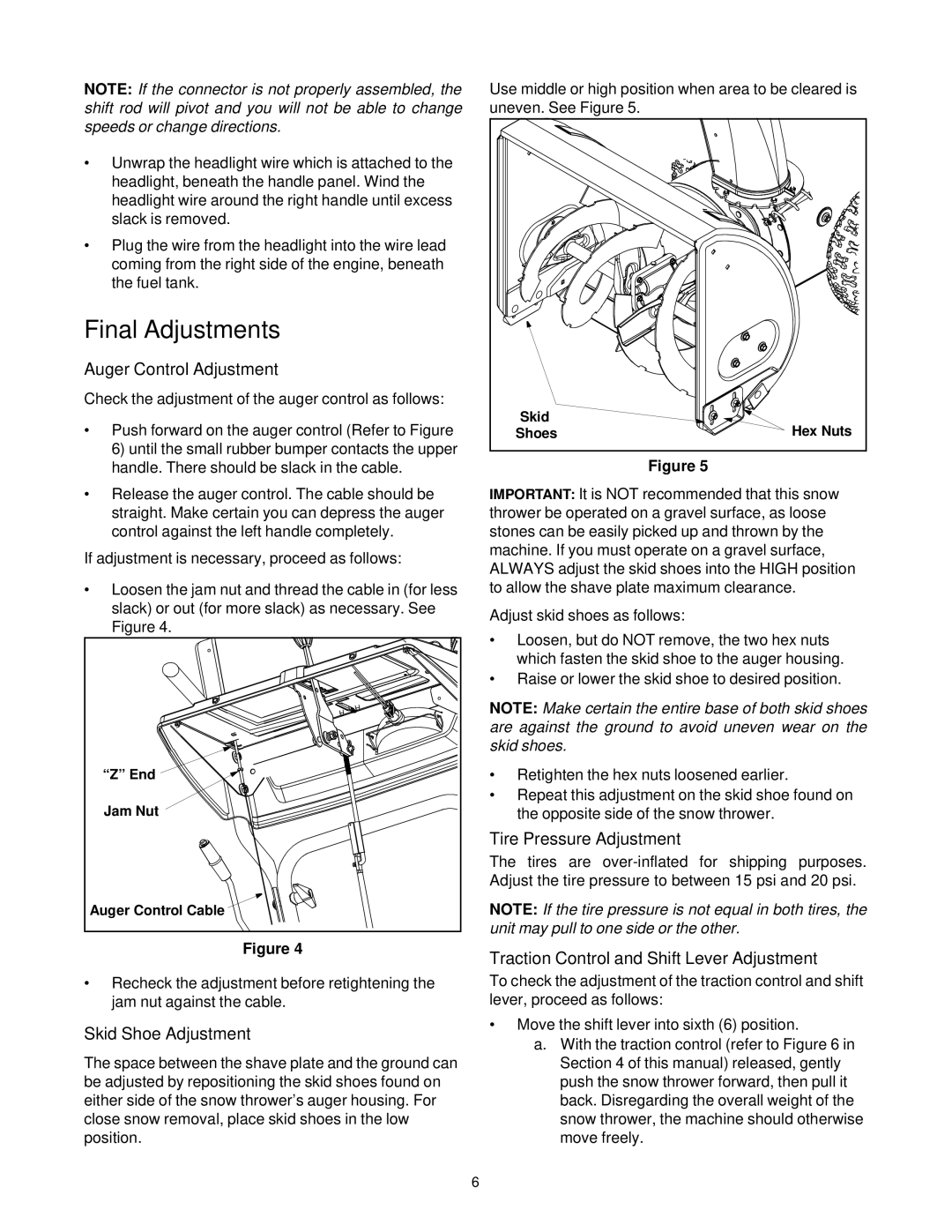
Use middle or high position when area to be cleared is uneven. See Figure 5.
Skid | Hex Nuts |
Shoes |
Figure 5
IMPORTANT: It is NOT recommended that this snow thrower be operated on a gravel surface, as loose stones can be easily picked up and thrown by the machine. If you must operate on a gravel surface, ALWAYS adjust the skid shoes into the HIGH position to allow the shave plate maximum clearance.
Adjust skid shoes as follows:
•Loosen, but do NOT remove, the two hex nuts which fasten the skid shoe to the auger housing.
•Raise or lower the skid shoe to desired position.
NOTE: Make certain the entire base of both skid shoes are against the ground to avoid uneven wear on the skid shoes.
•Retighten the hex nuts loosened earlier.
•Repeat this adjustment on the skid shoe found on the opposite side of the snow thrower.
Tire Pressure Adjustment
The tires are
NOTE: If the tire pressure is not equal in both tires, the unit may pull to one side or the other.
Traction Control and Shift Lever Adjustment
To check the adjustment of the traction control and shift lever, proceed as follows:
•Move the shift lever into sixth (6) position.
a.With the traction control (refer to Figure 6 in Section 4 of this manual) released, gently push the snow thrower forward, then pull it back. Disregarding the overall weight of the snow thrower, the machine should otherwise move freely.
6